

Corne CRKBD Build Log
The hardest keyboard I've ever tried to build
Before jumping to pictures and build steps, I'd encourage you to read the bottom of this post first where I talk about everything that I did wrong so hopefully you won't get caught out too! This is probably the most complicated keyboard that I've built and I made the mistake of being a bit cavalier at first and paid the price.
Don't be put off by this warning though; this board was a ton of fun to make and I learned a lot. I hope you do too!
I've had my eye on the Corne keyboard for a while now. For those of you who know me or have read this blog before will be aware of my love of tiny keyboards. I built my first tiny keyboard a few years ago and very quickly progressed to split keyboards leading me to build a 'Let's Split'. I find keyboards with this grid (referred to as 'ortholinear') layout super comfortable and ergonomic to type with and the idea of staggering these columns to fit your fingers intrigued me a lot.
ENTER CORNE!
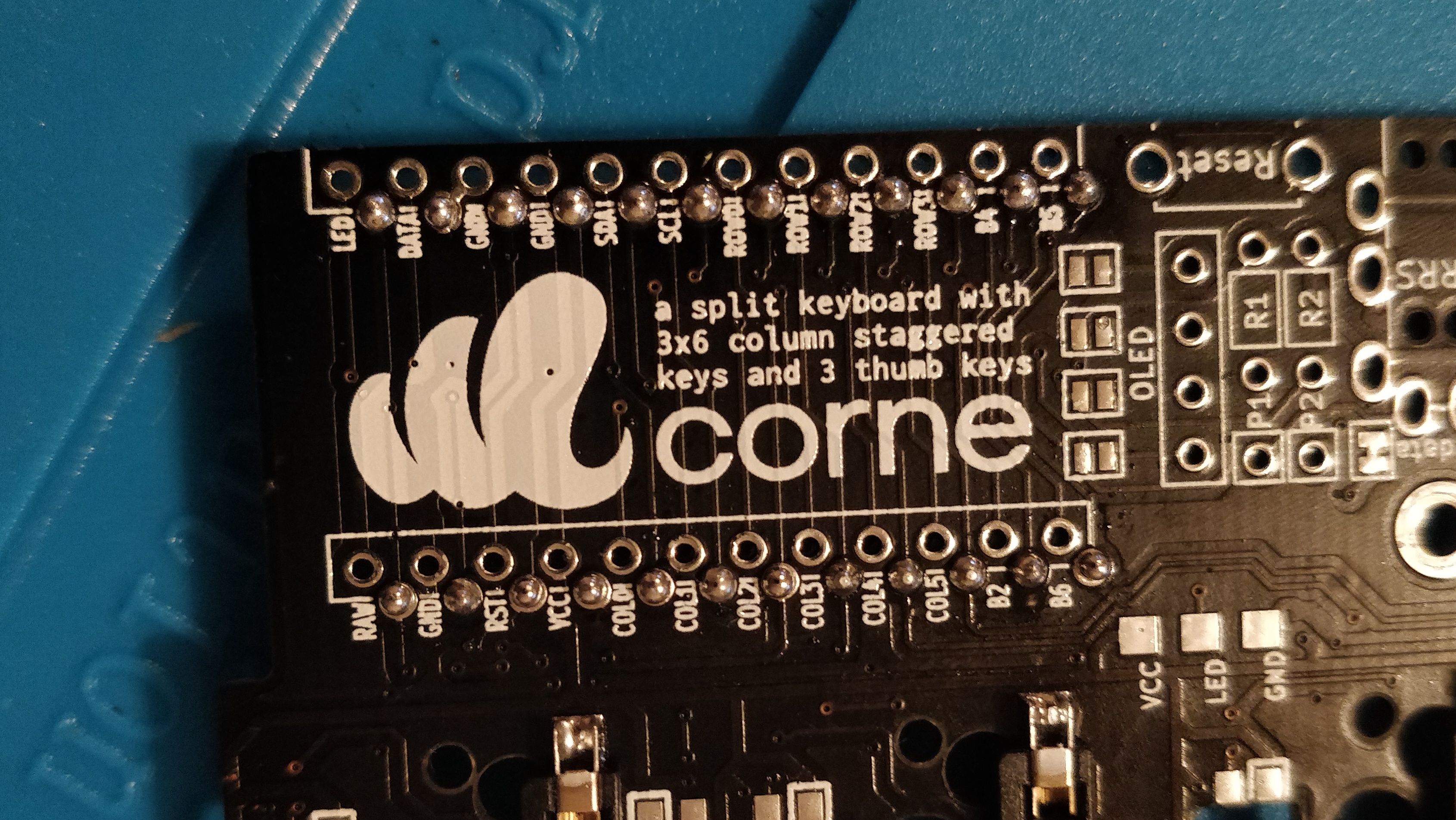
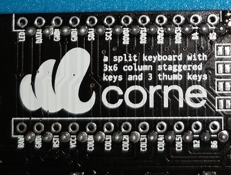
The Corne Keyboard (often referred to as a Crkbd or Helidox) takes these ortholinear design and ergonomic principals and staggers the key columns them which means that you're required to move your fingers even less to type! How exciting 🤩
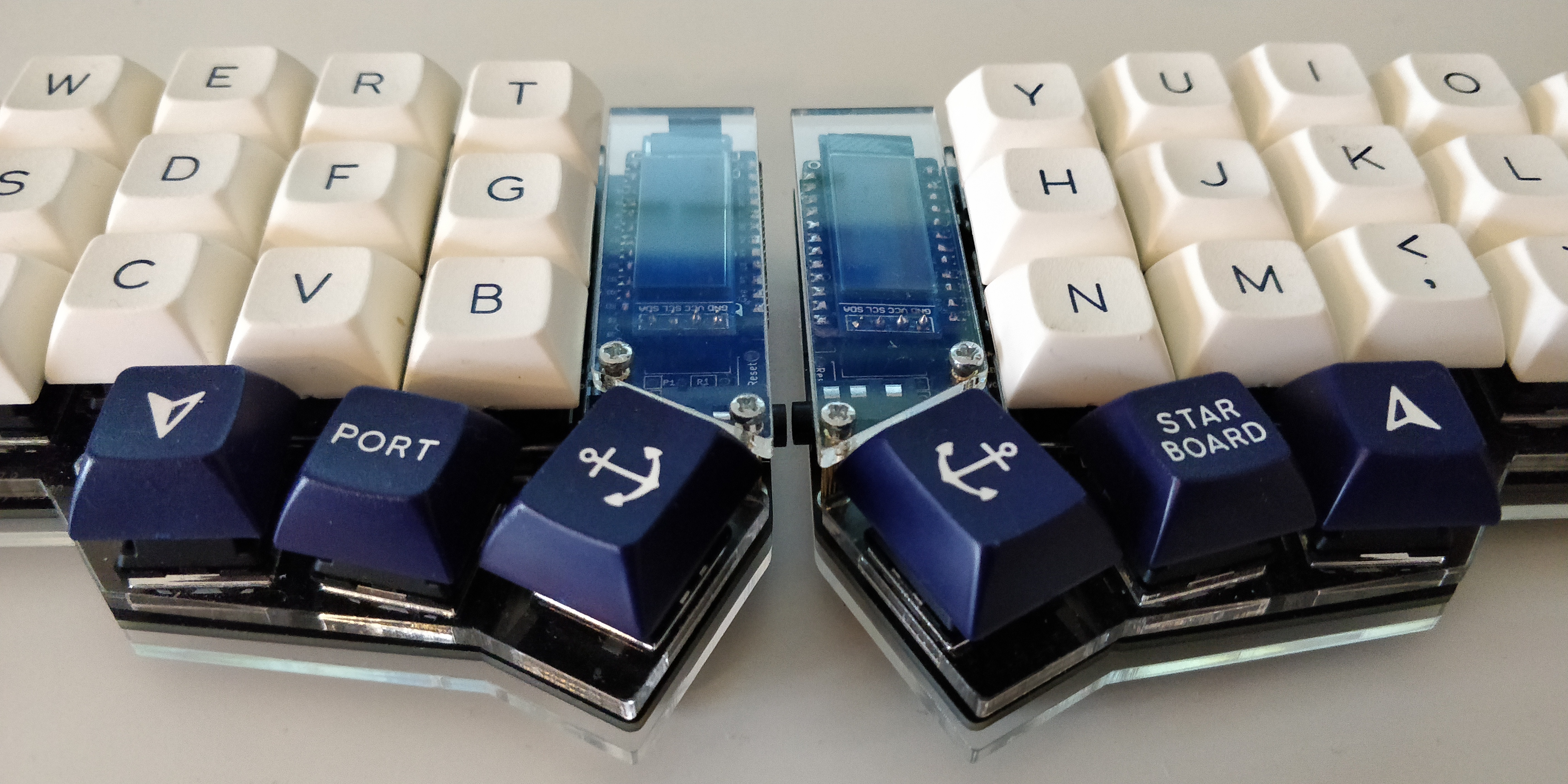
This is another split 40% keyboard with 42 keys overall and 3x6 column staggered layout (unless you choose to break the end columns off to make it even smaller!). It also comes with the ability to attach OLED screens to each half. While not particularly useful aside from debugging the build as you go, it's a really cool aesthetic and a super fun gimmick. You can either keep the default displays that the firmware comes with, load on your own graphics, or add any of the growing number of open-source projects made by others in the community.
If you haven't stumbled across this blog post specifically to learn how to build one, I hope that this has convinced you!
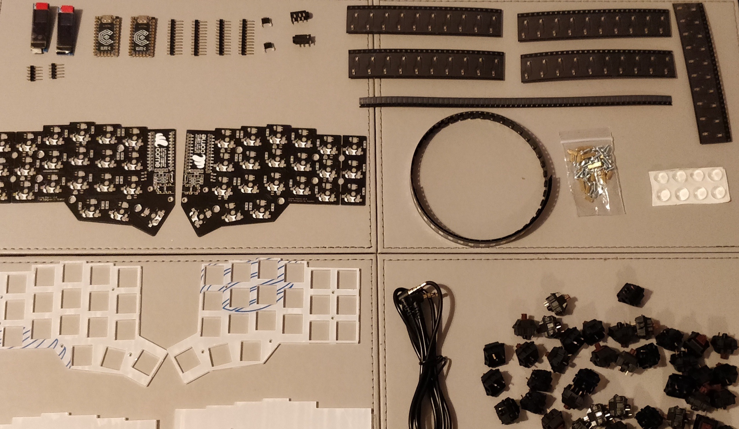
Parts required
Several websites will provide the following parts for you such as mechboards but in case you wanted to source the parts for cheaper you will need:
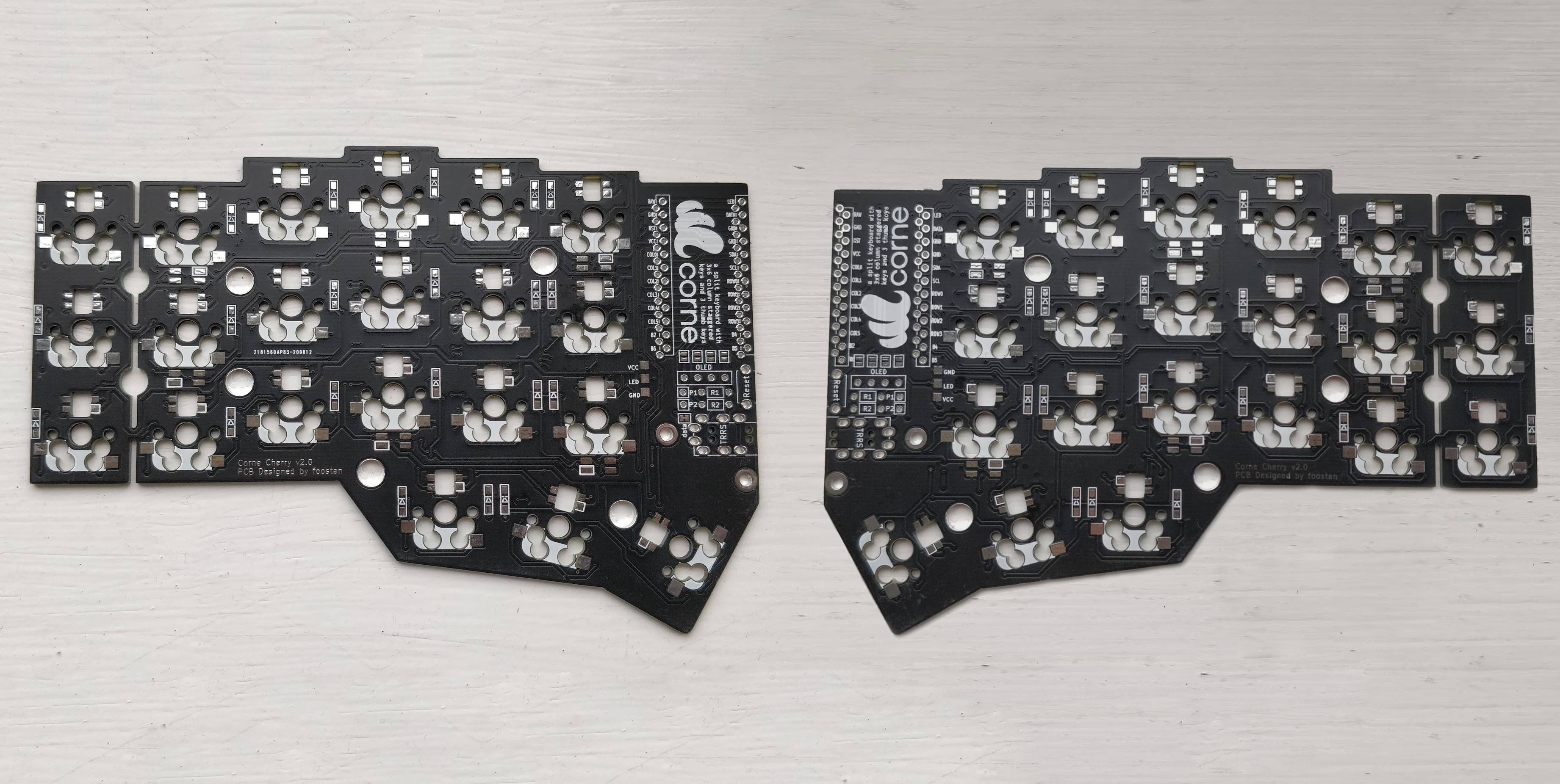
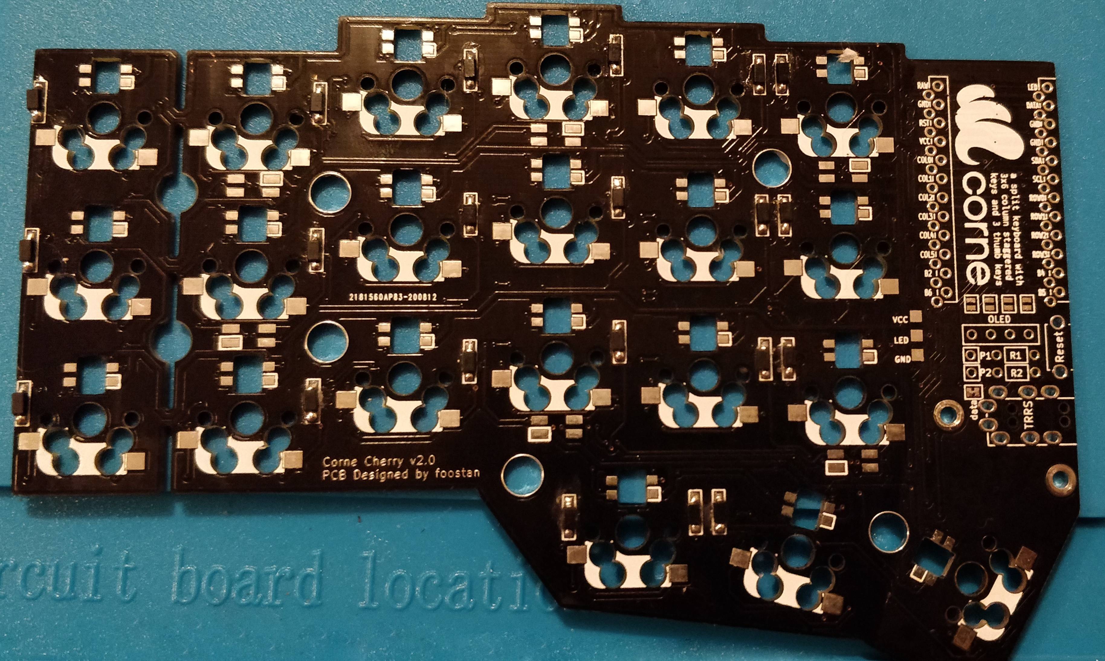
- 2 × Corne PCB (can be bought from websites or printed using open-source designs on github)
- 2 x microcontrollers (I used Elite-C but Pro Micros/similar compatibility will be fine)
- 42 × Diode (SMD)
- 42 × Kailh MX Hotswap socket
- 42 x MX switches
- 2 × TRRS jacks
- TRRS table
- 2 x acrylic plate sets (can be bought from websites or printed using open-source designs on github)
- 4 × 8mm M2 standoffs for the OLED screen guards.
- 10 × 6mm M2 spacers for the main acrylic plates
- 28 × M2 screws
- USB cable (will differ depending on your microcontroller)
- Ultra Low profile Mill-Max Header sockets, header connectors, connector pins for socketing the microcontroller (optional but recommended for easy removal)
- 2 × Reset buttons (optional)
- 2 OLED screens (optional)
Equipment required
- Soldering iron
- Solder
- Tweezers
- Screwdriver
- Pliars (optional but recommended)
- Solder removal pump (optional but recommended)
- Flux (optional)
- Isopropyl alcohol and a toothbrush for cleaning flux residue (optional but advised if you used flux)
- Helping hand for desoldering (optional)
Now... We Build!
This keyboard is a split keyboard. To keep this build log as simple and succinct as possible I'll only be showing how to build one half. You will then have to repeat the steps again for the other half. I would recommend not doing both halves in parallel in case you make the same mistake twice; It will be a lot easier to correct if you realise you have done something wrong only once.
Before we begin, another reminder to scroll to the bottom of this post to check out the mistakes that I made originally so that you can learn from them and not do what I did. This project became a lot more expensive and time-consuming than it should have been because I wasn't paying attention. Let's start!
Step 1. Preparing the diodes
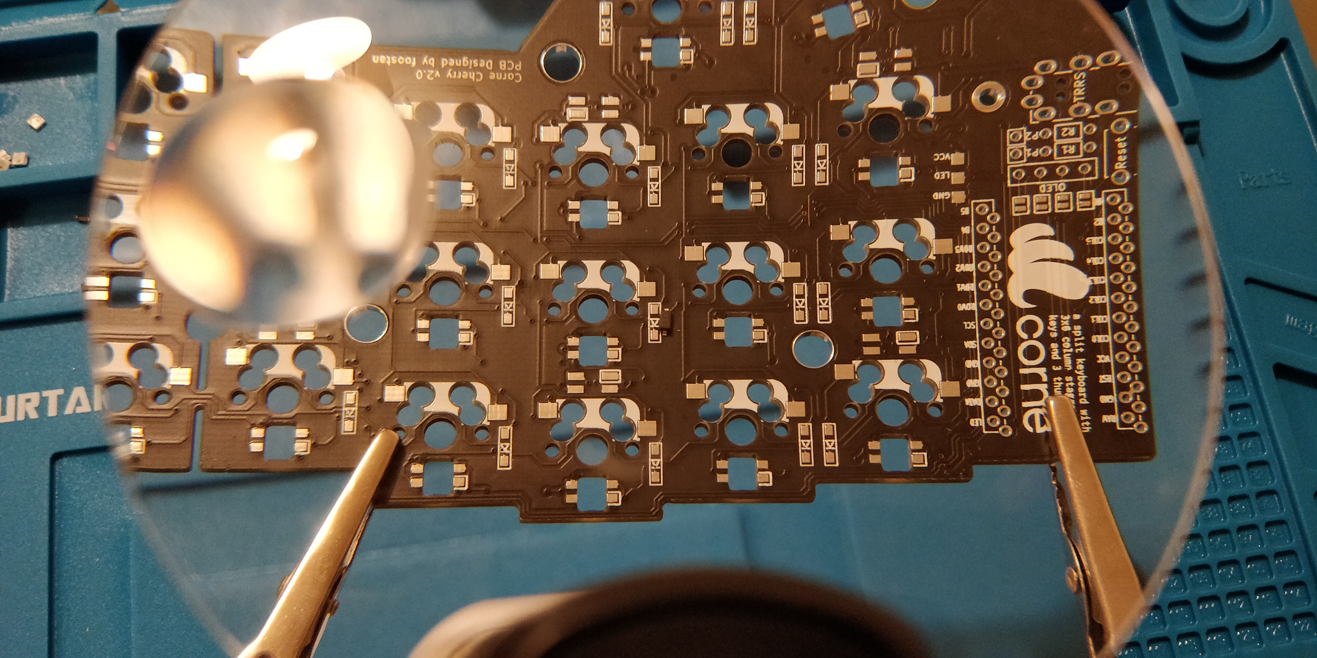
The diodes are tiny and the smallest component on this board that you'll need to work with, but they become easier to work with the more you do it. Marked out on the board is 20 rectangular boxes where the diodes will go.

Diodes only work in one direction and helpfully there are solid lines on both the diode and in the boxes on the PCB. They're facing the correct way when these lines both match up. I had to use a magnifying glass for this at times as the diode's line wasn't too obvious. I also recommend using tweezers for moving them around as handling them with your fingers is quite challenging!
Step 2. Applying flux for the diodes
Using flux is super helpful when soldering. It promotes the flow of solder and makes it automatically 'stick' to the tiny pads. I found it helpful to use it for these diode pads due to how small they are and applied a little blob using a cotton bud. Don't worry about how messy it will look - we'll clean the excess off later.
The best technique for this is to pre-solder one half of each pad so that you have a free hand to hold your tweezers for positioning the diode. Then you can heat the solder to reflow it around the diode with your other hand. Once you've done this you can then solder the other side of the diode without fear of it moving around.
Repeat this 20 times to complete the first half.
Step 3. Pre-solder the Hotswap socket pads
Much like the diodes, it's recommended to pre-solder the hot-swap socket pads. You can go ahead for pre-solder both sides this time. This will make it a lot easier to position the sockets and re-flow the solder to allow it to slide into PCB holes and to lock it into place.
Step 4. Give the flux a bit of a clean
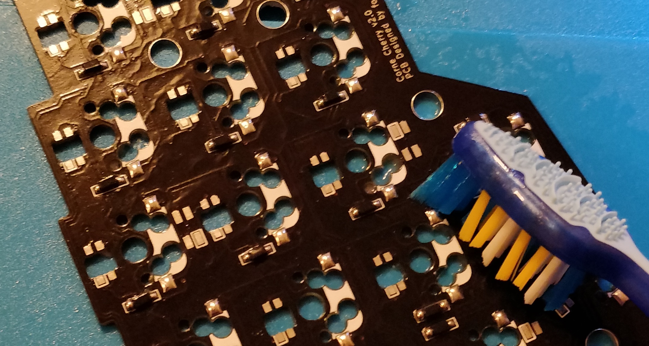
Depending on which flux you use, at worst it can be corrosive to the components and at best it's just sticky... Let's clean it off. The reason I'm doing it now is that I've done most of the surface-mounted component soldering and no longer need it. It's easier to clean it off now before the hot-swap sockets get in the way.
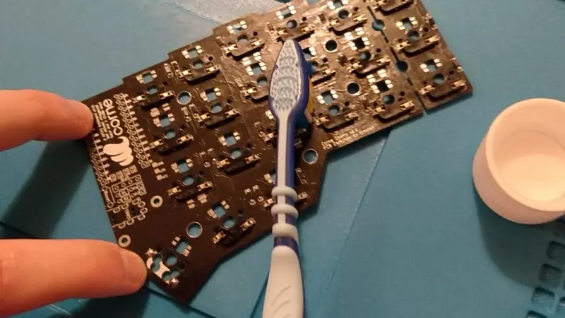
Grab a toothbrush, dip it in isopropyl alcohol and give it a scrub. You shouldn't need to scrub it too hard, but do it hard enough with enough alcohol that it breaks up the flux and starts to evaporate. You should be left with a nice clean board with nice clean solder joints. Nice.
Step 5. Solder the hot-swap sockets into place
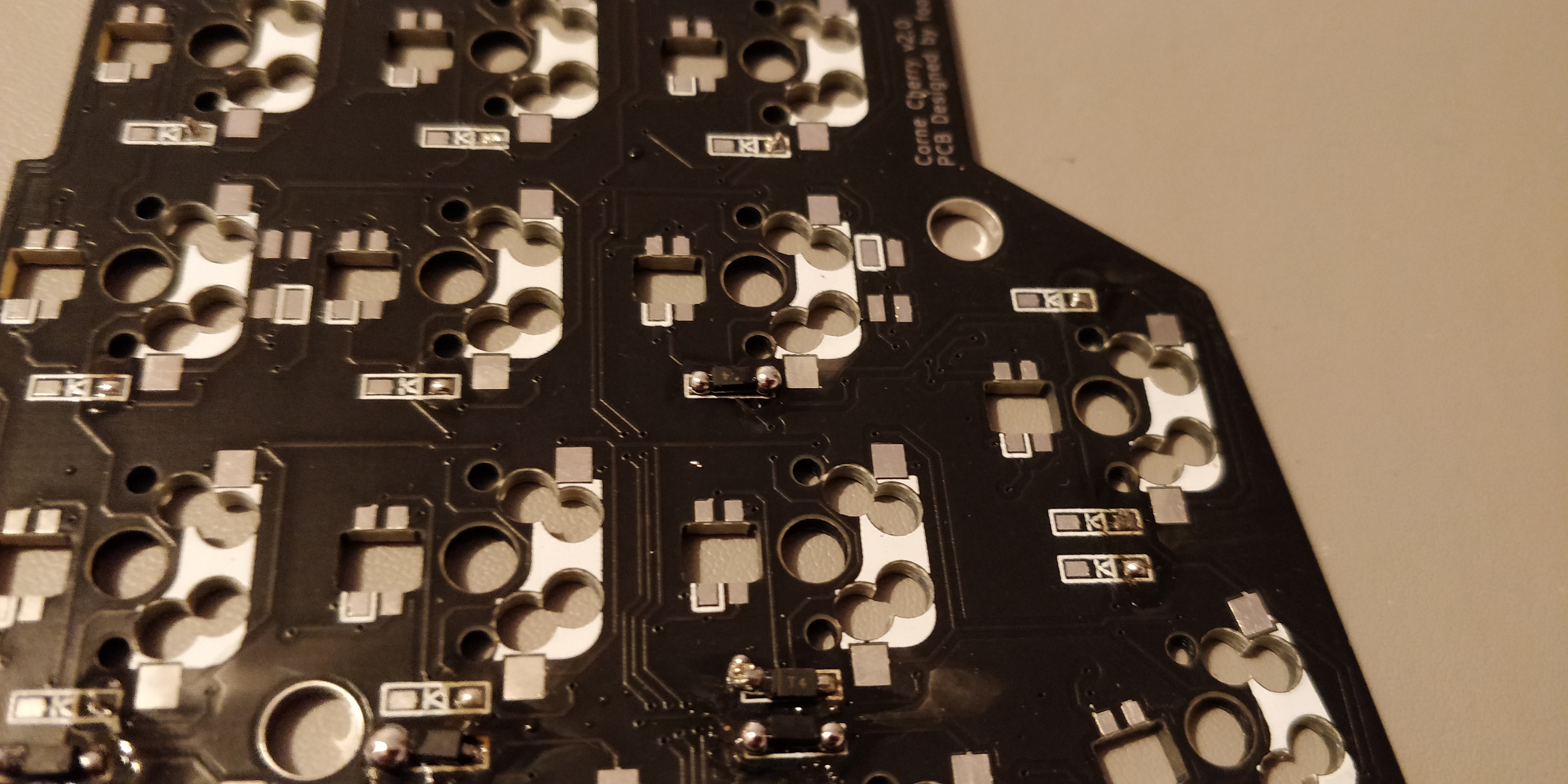
In the previous step, I pre-soldered the pads ready to place the hot-swap sockets on top. In the picture above, the socket is just resting on top of the solder. With one hand, hold the socket in place with some tweezers, and with your soldering iron gentle apply some force on the socket connector. The heat from the iron will reflow the solder and it should bind the connection with the socket. You should feel a 'bump' as one half of the socket falls into place. Repeat this for the other side and for the remaining 20 sockets on this half of the board.
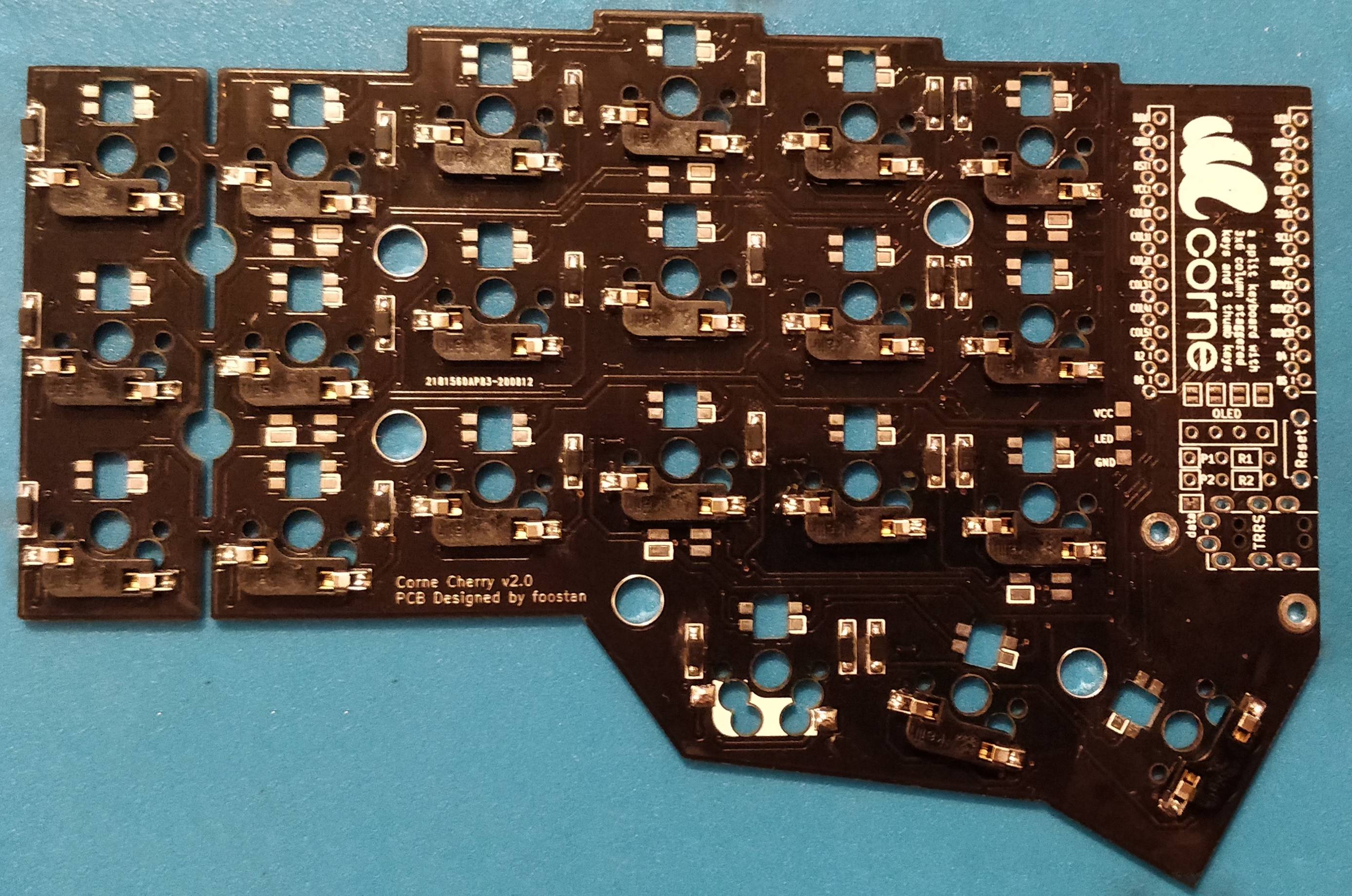
Once complete, the underside of the board should look like the one in the image above! If there is any remaining flux it might be a good idea to give it another scrub now.
The eagle-eyed among you might notice that I missed a socket along the bottom. I discovered this at the very end but I had already taken the photos! Whoops. Moving on...
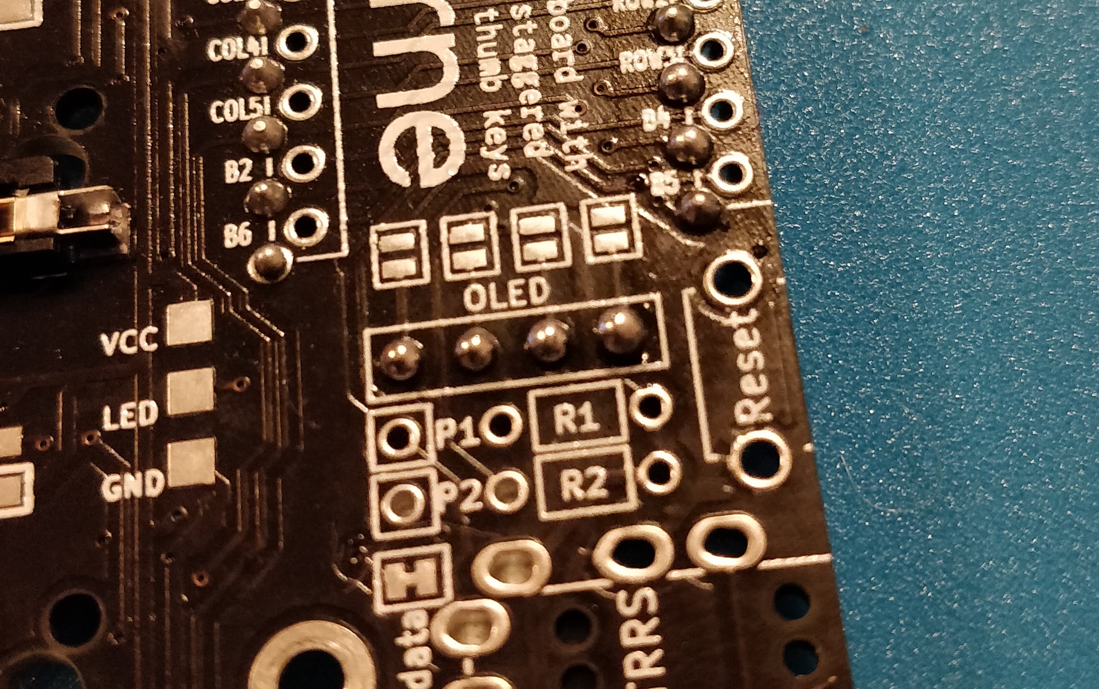
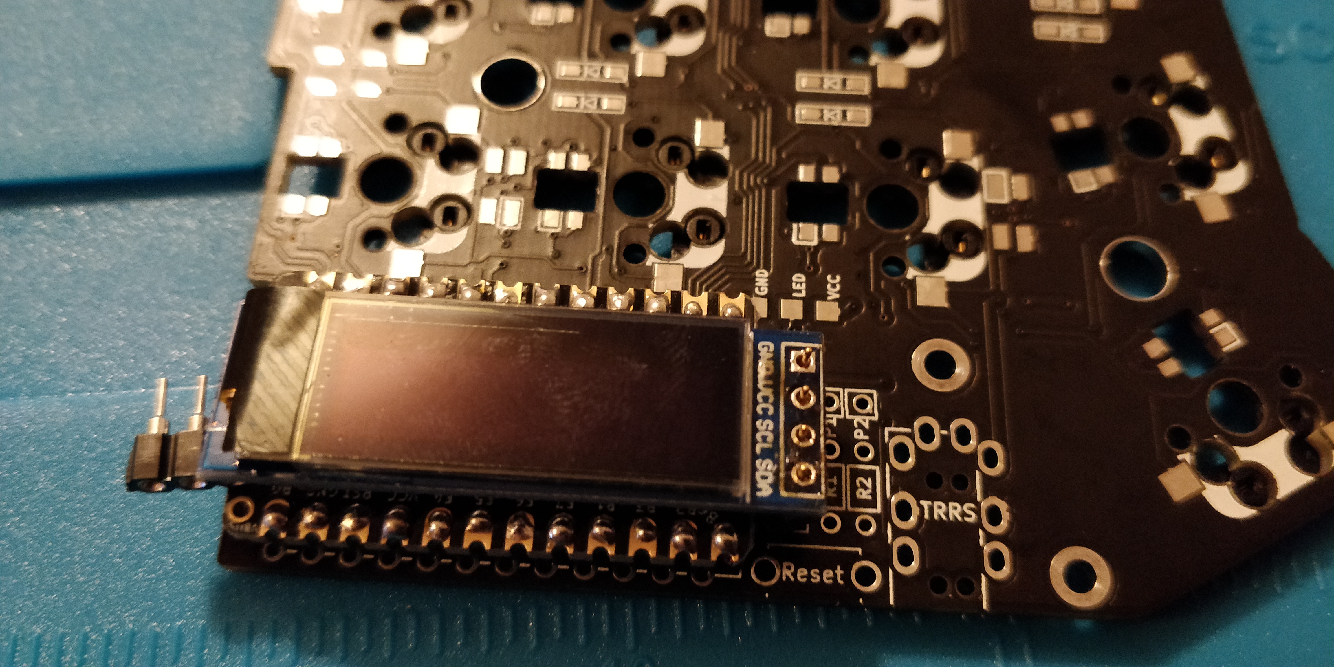
Step 6. Solder the OLED jumper pads
The OLED screen isn't a necessary part of the build, but it's a good idea to solder the jumpers anyway. You can disable the OLED in the firmware if you didn't want to use it but if in the future you decide that you want to use an OLED screen then you'll have to remove the microcontroller to solder the jumper pads.
Make sure that you short circuit the jumper pads and connect both halves. I wouldn't recommend using flux for this as it might make it difficult to bridge the gap between the pads.
Step 7. Secure the microcontroller headers/sockets
You have two options on how approach soldering your microcontroller. I'll outline the two first.
The first is to solder the header pins that will come with your Pro Micro or Elite-C to the PCB. You will then be able to solder the microcontroller to the top of the pins to secure it in place. This isn't advisable due to it being more permanent.
The second option is to use sockets. If you have the time and energy, I'd recommend reading this article first on the benefits of socketing a microcontroller and how it works but basically, it will allow you to remove the component whenever you want. If you've ever had to desolder a microcontroller then you'll know why this technique is so freaking helpful.
For this guide, I'll be using the second option and socketing the microcontroller and OLED screen using ultra-low profile Mill-Max Header sockets, header connectors and connector pins. We want the microcontroller as close to the board as possible. If you just want to use the standard headers then go ahead and skip to step 12.
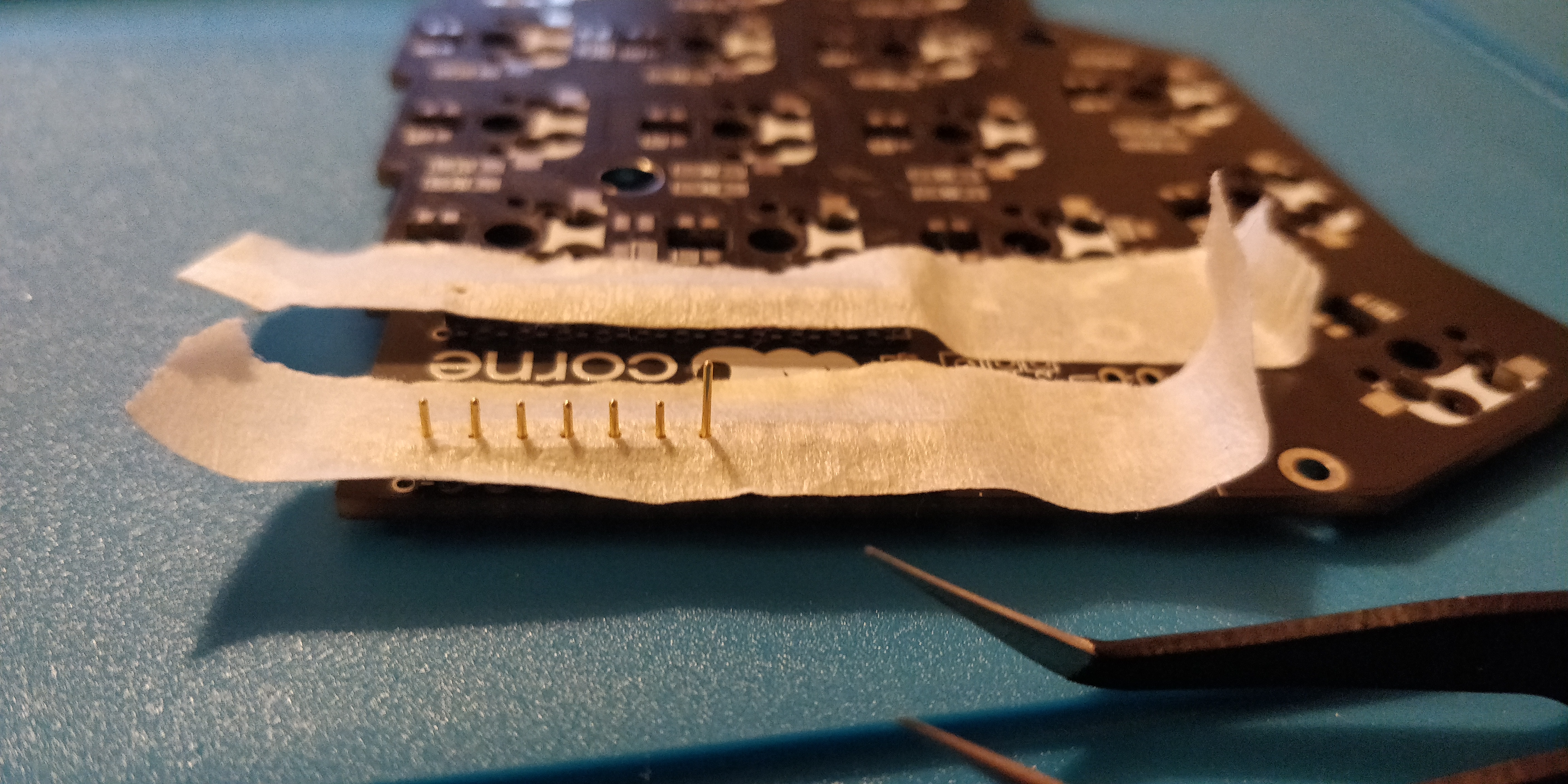
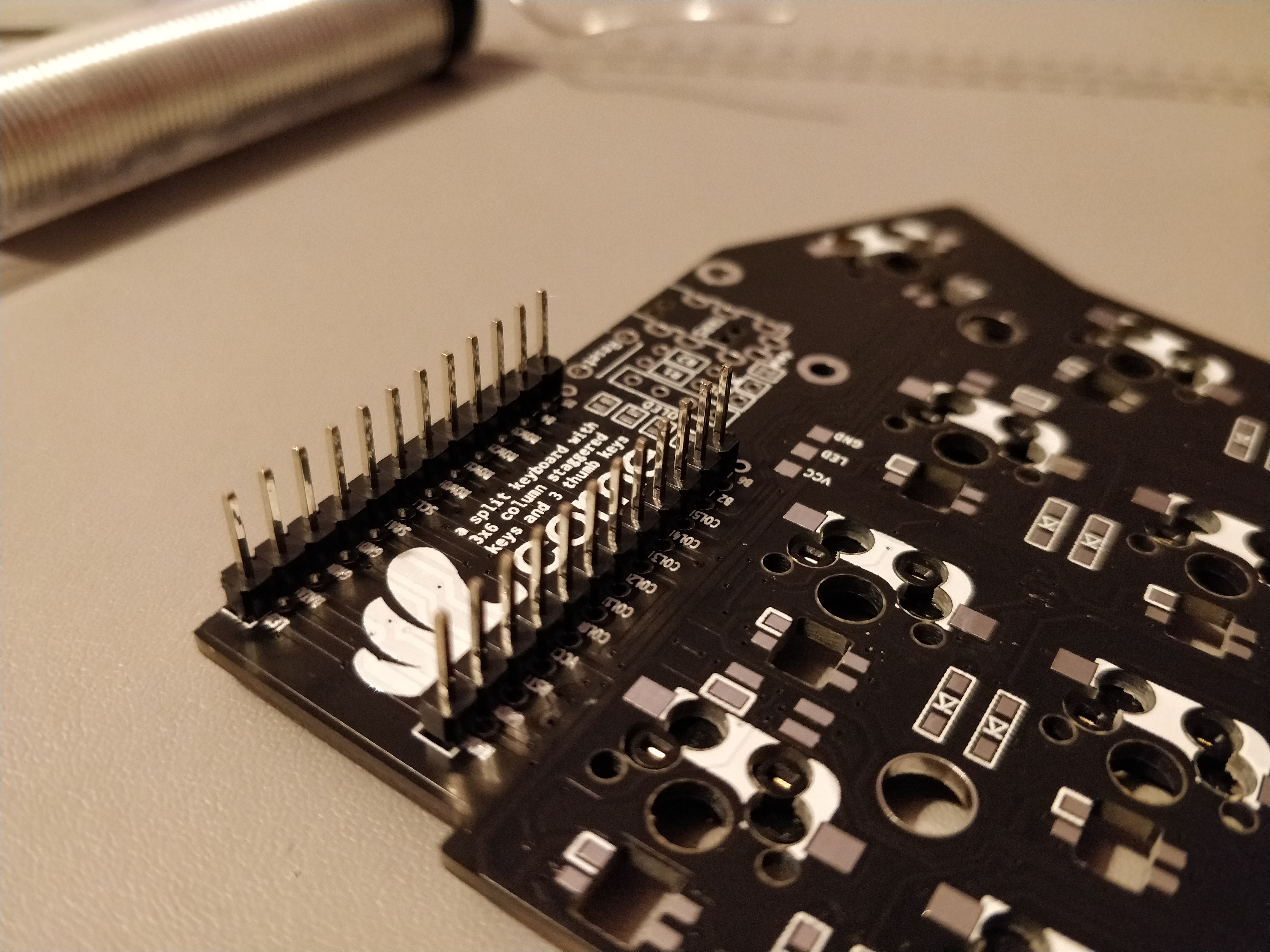
With that said, tape two header socket rows of 12 in place to the top of the board (the opposite side to the diodes and hot-swap sockets) so that they're secure and level and let's get soldering!
Step 8. Solder the socket pins
Flip the board back over so that we're once again soldering on the back of the board where the diodes are and carefully solder each pin making sure to get a good solid joint and not bridging any connections. A good tip is to solder each corner first while ensuring that it's level and in place.
Step 9. Place pins in the microcontroller sockets
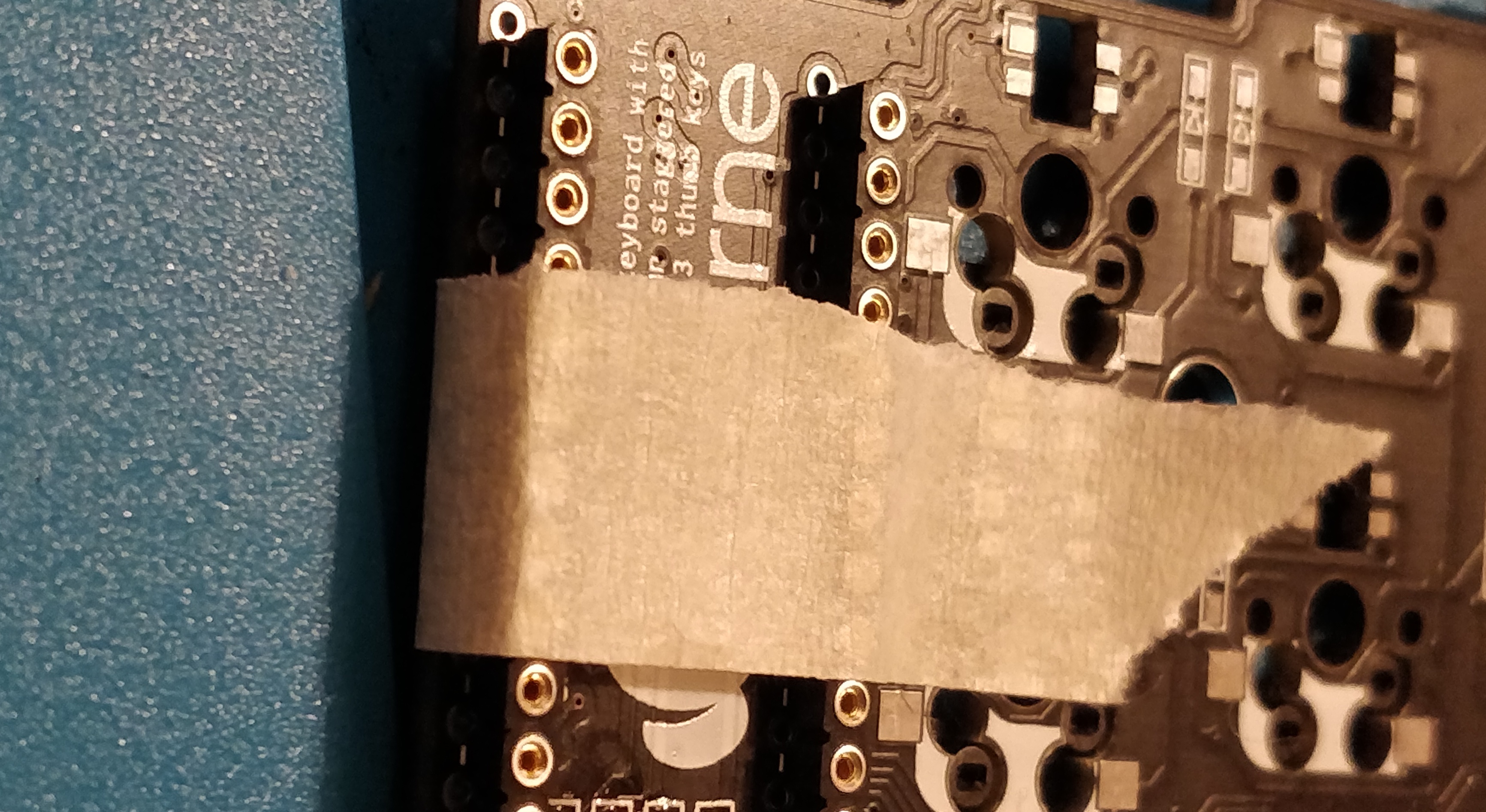
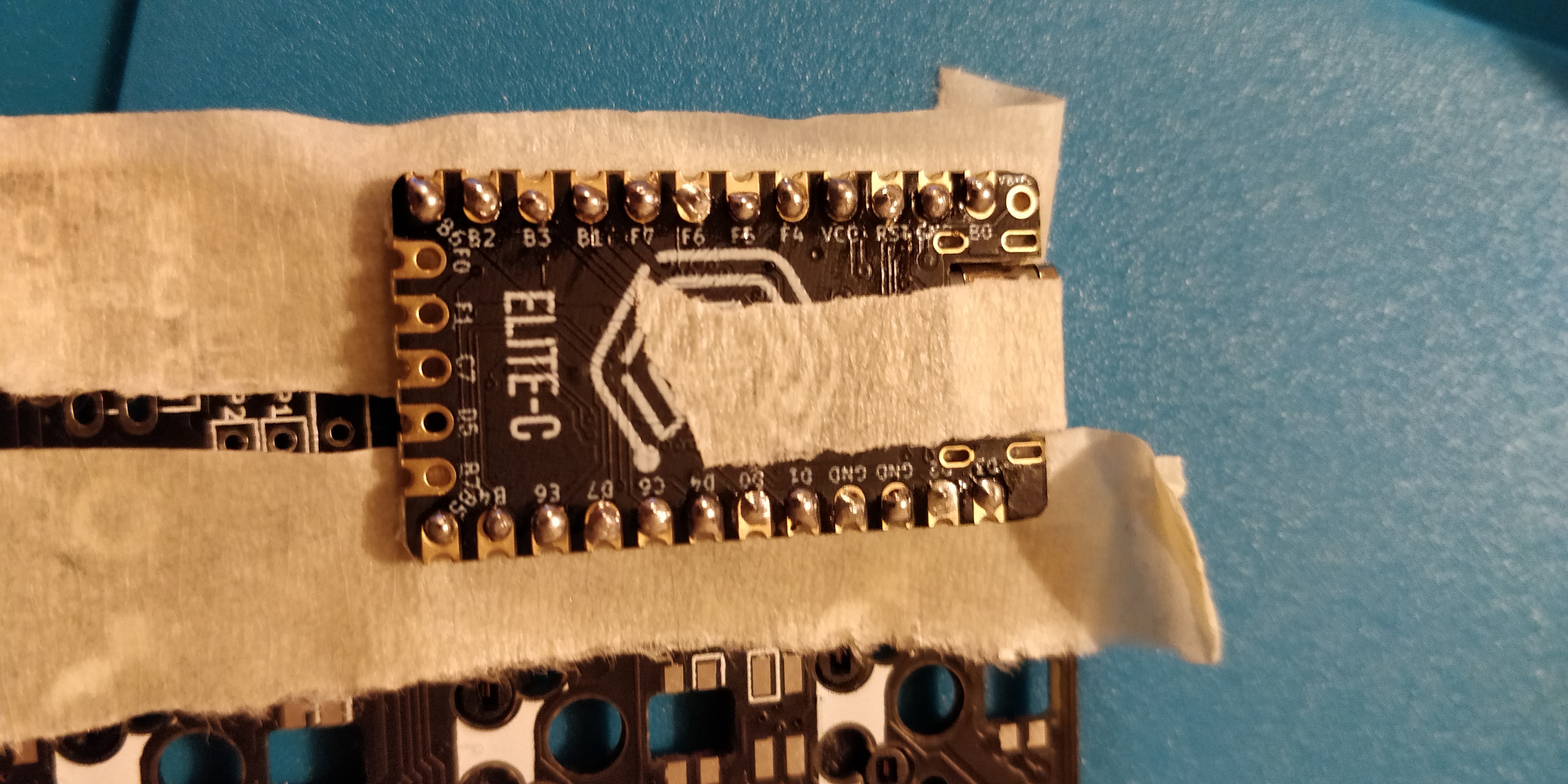
Now we'll need to slot the connector pins into the sockets that have just been soldered. I covered the sockets with tape to prevent the solder that I'll do in the next step from fusing the connection. We want to remove these pins later on and accidental solder leakages will make that very difficult. I used Mill-Max pins for this as they're more solid and already the correct length but diode legs work too, so you can go ahead and cut the legs off 12 diodes to get 24 pins.
I'd recommend using tweezers or even pliers to do this. Basically whatever allows you to get a good enough grip to allow you to push the pins into place. They're very sharp and can easily pierce the skin. There's definitely a 'wiggling' technique to this and you'll likely get better at it the more you do but several of mine self-ejected from the socket due to me pushing at the wrong angle. This sent them flying across the room so be prepared for a scavenger hunt...
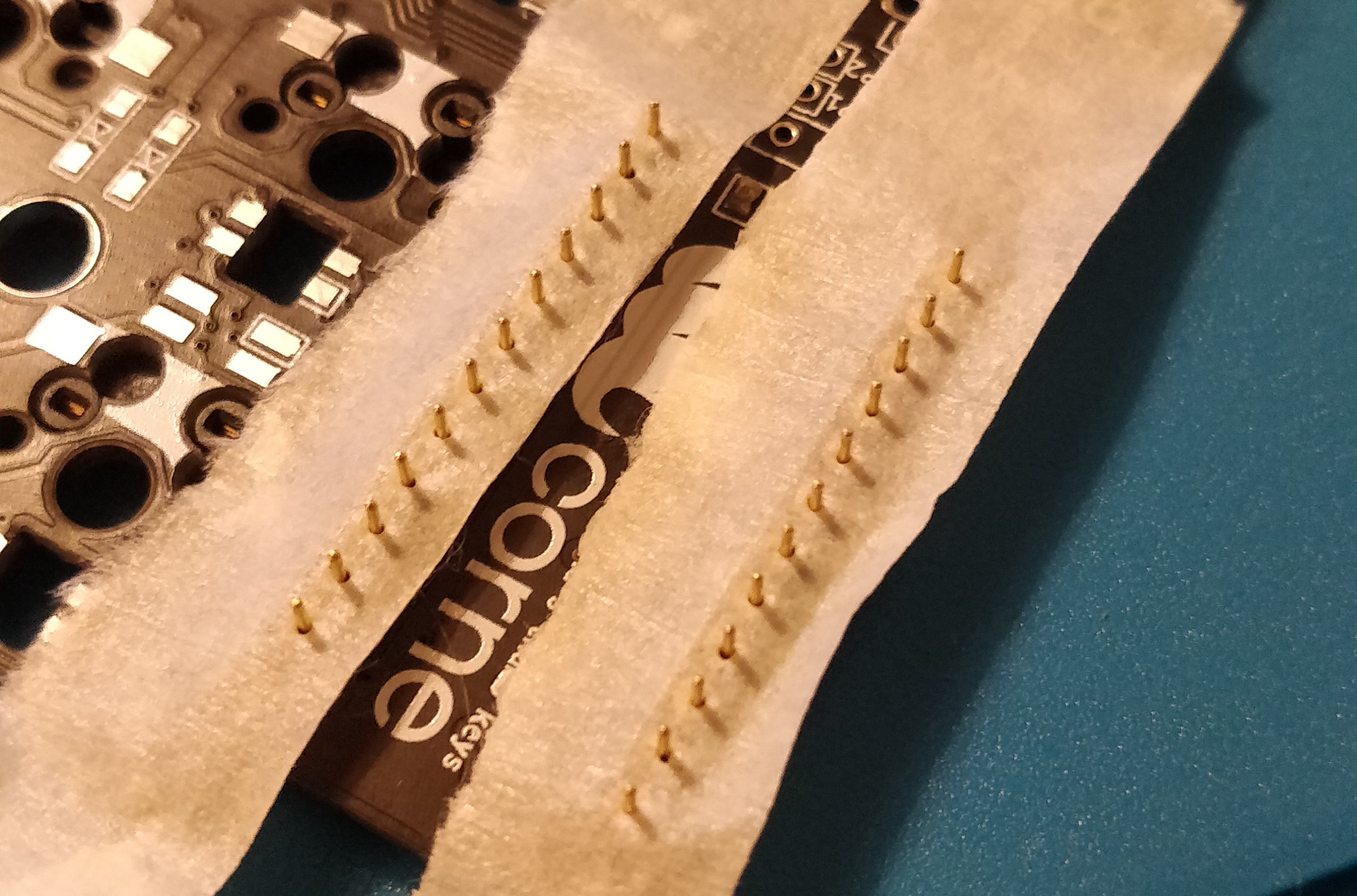
Once all pins have been inserted it's a good idea to turn them upside down and gently push against a flat surface to ensure that they're all full inserted.
Step 10. Solder microcontroller to the pins
To complete the socketing of the microcontroller, place the microcontroller over the pins being very careful that it's the correct way up. Hold it in place and solder. Elite-C microcontrollers are super thin and still leave clearance from the PCB, but depending on your microcontroller you may need to temporarily wedge something between it and the PCB to give the clearance necessary before soldering.
Once the connector pins have been soldered, trim off any extra height. Congratulations, we have just socketed the microcontroller! 🎉
Step 11. Remove the microcontroller
The microcontroller can now be safely and carefully removed to give us more room to work with. This can be inserted back into place with ease at a later stage.
With a blunt object, slot it carefully under the microcontroller and ease it upwards to eject it from the sockets. Don't worry if any pins have bent in the process, you can bend them back using pliers or carefully with tweezers. You can also go ahead and remove the tape covering the socket holes as it's no longer needed.
Step 12. Tape down a row of four socket headers for the OLED display
Follow the same process of taping down the microcontroller sockets for the OLED sockets. Tape down a row of 4 and secure in place.
Flip the board over to once again solder the OLED header sockets. You can then go ahead and remove the tape that was securing it in place as we don't need to insert pin connectors this time.
Step 13. Preparing the OLED for socketing
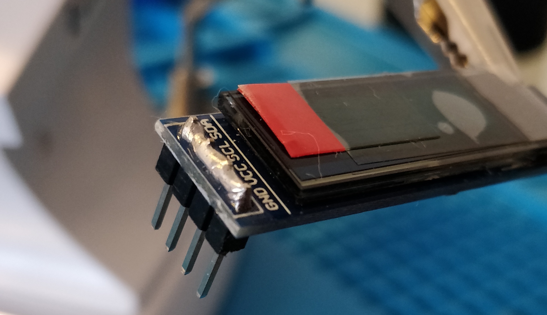
The sockets that we have just soldered for the OLED display are not compatible with the header pins that normally come pre-soldered to it. I'm going to desolder these header pins and use Mill-Max connectors. If your OLED screen does not have these headers already attached then lucky you! You can skip these next few steps and jump to step 16.
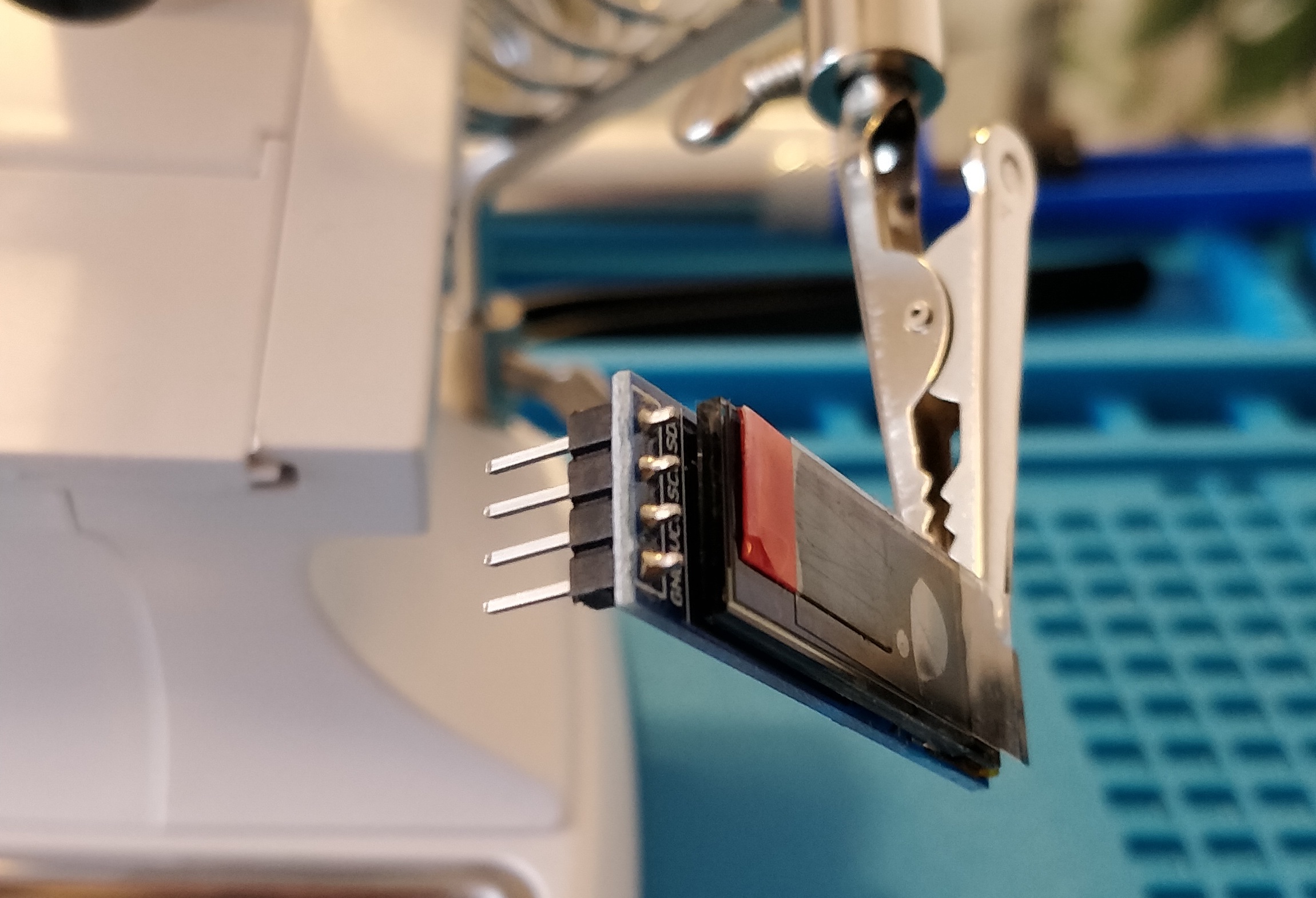
Desoldering is the process of removing solder from a joint to remove a component. I used my helping hand tool to grip the OLED allowing me to use both hands to desolder. You may have your own technique of desoldering and that's absolutely fine but this worked for me.
Step 14. Cover and connect the OLED pins with solder for easy pin removal
Desoldering is a pain. There are lots of tools at your disposal such as desoldering wick, braid or pumps. It may seem counterintuitive but it's far easier to remove these pins by covering them with solder so that we can apply heat evenly.
Step 15. Heat the solder and ease out the header pins
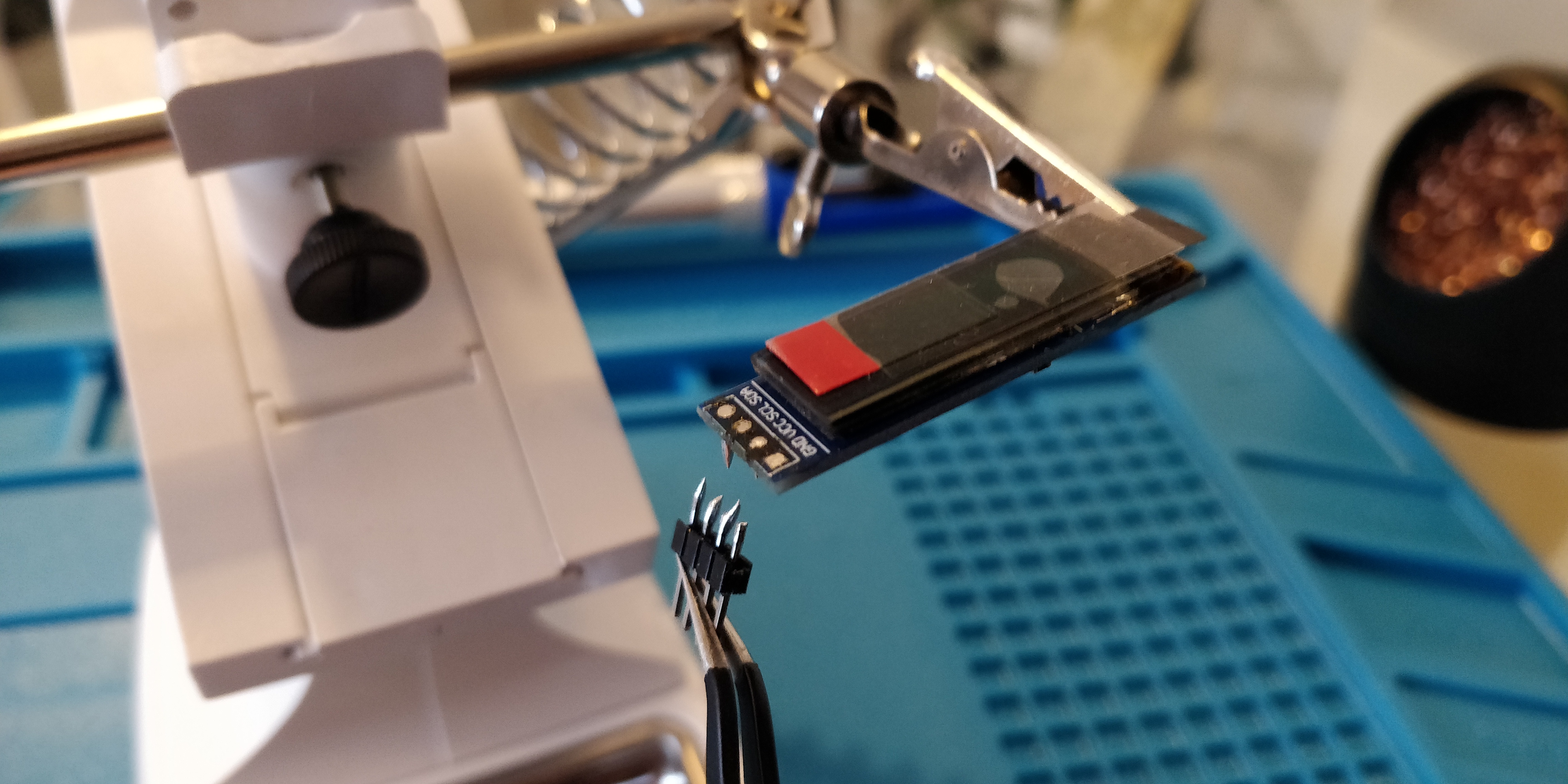
All four of these pins are going to need to come out at the same time. Once the solder has been applied to connect them all together, use your iron to heat the solder up and with your other hand you can use tweezers to carefully ease the header pins out. This should happen fairly easy if the solder is hot enough.
You may be left with some excess solder so you can go ahead and remove this with wick, braid or a solder pump. Desoldering is a bit of an art so I'd advise you to watch some youtube videos on different techniques if you aren't sure as that deserves a whole blog post to itself. You should be left with a clean OLED with holes ready for new connector pins.
Step 16. Prepare the new connector pins
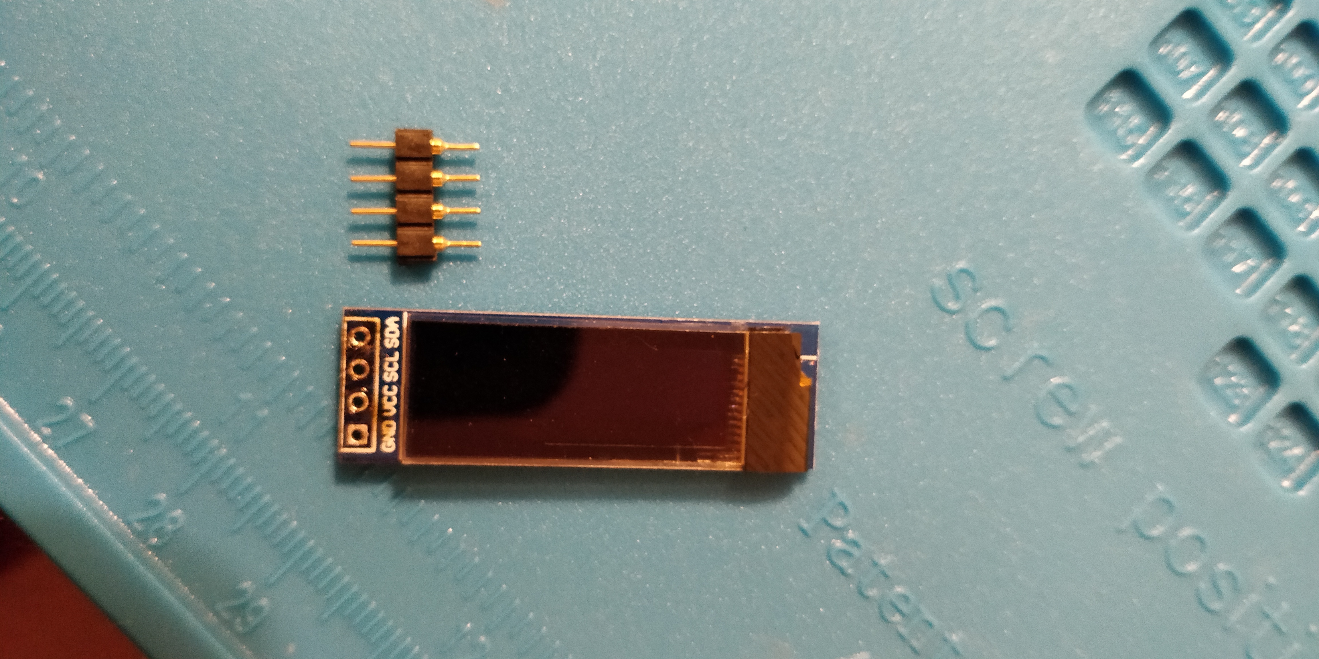
Once the solder has been cleaned up, prepare a row of four connector pins to solder. These will slot through the OLED display holes and into the sockets on the board that we soldered in step 12.
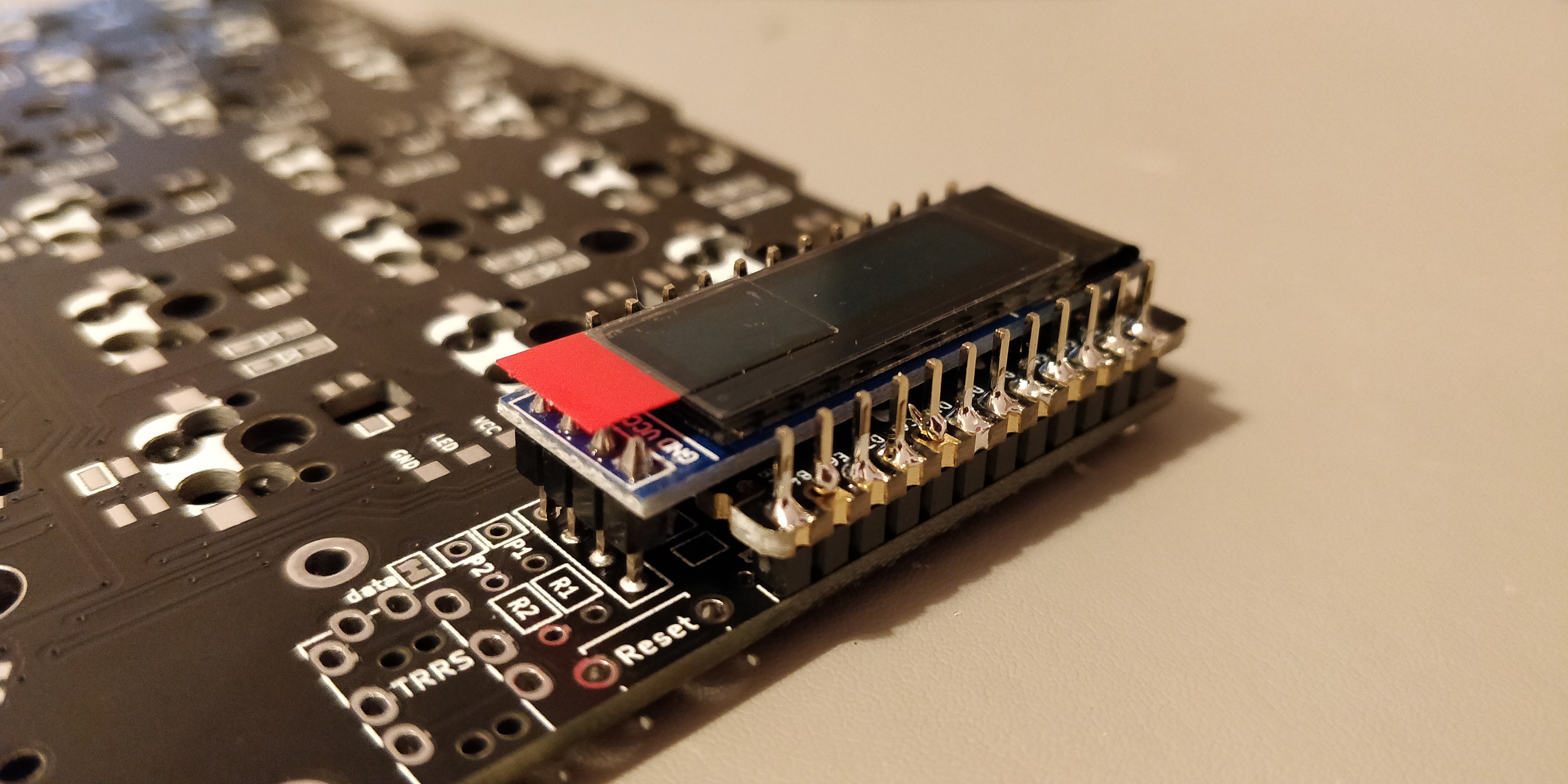
Step 17. Temporarily create a space divider to solder the OLED in place
The microcontroller can now be carefully reinserted into the sockets, the connectors can be inserted into the OLED sockets and the OLED screen can be placed on top ready for soldering.

There is likely to be a gap between the top of the microcontroller and the OLED so to keep it straight for soldering it's a good idea to temporarily insert something between the two. I found that some leftover header sockets were the perfect thickness for this.
Once you're happy with the stability and angle of the OLED screen, solder the four connectors to the top of the OLED.
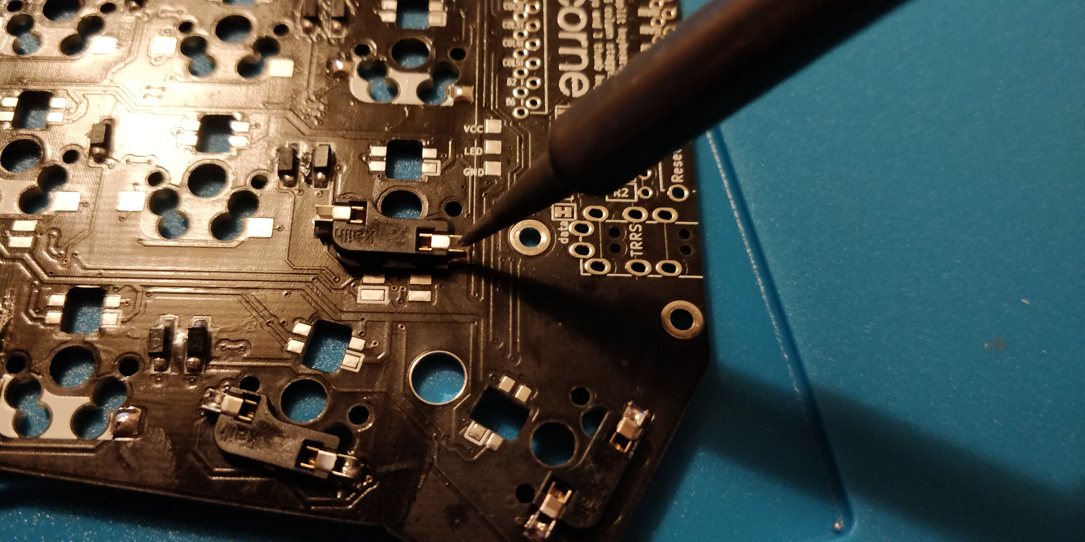
Step 18. Connect the power and test the switches!
If you haven't loaded the keyboard firmware onto the microcontroller yet, you should do this now. If this is your first time building keyboards I would recommend reading the tutorial on QMK. QMK provides devices such as keyboards the firmware necessary to interact with them. There are a few variations but QMK is a community and personal favourite.
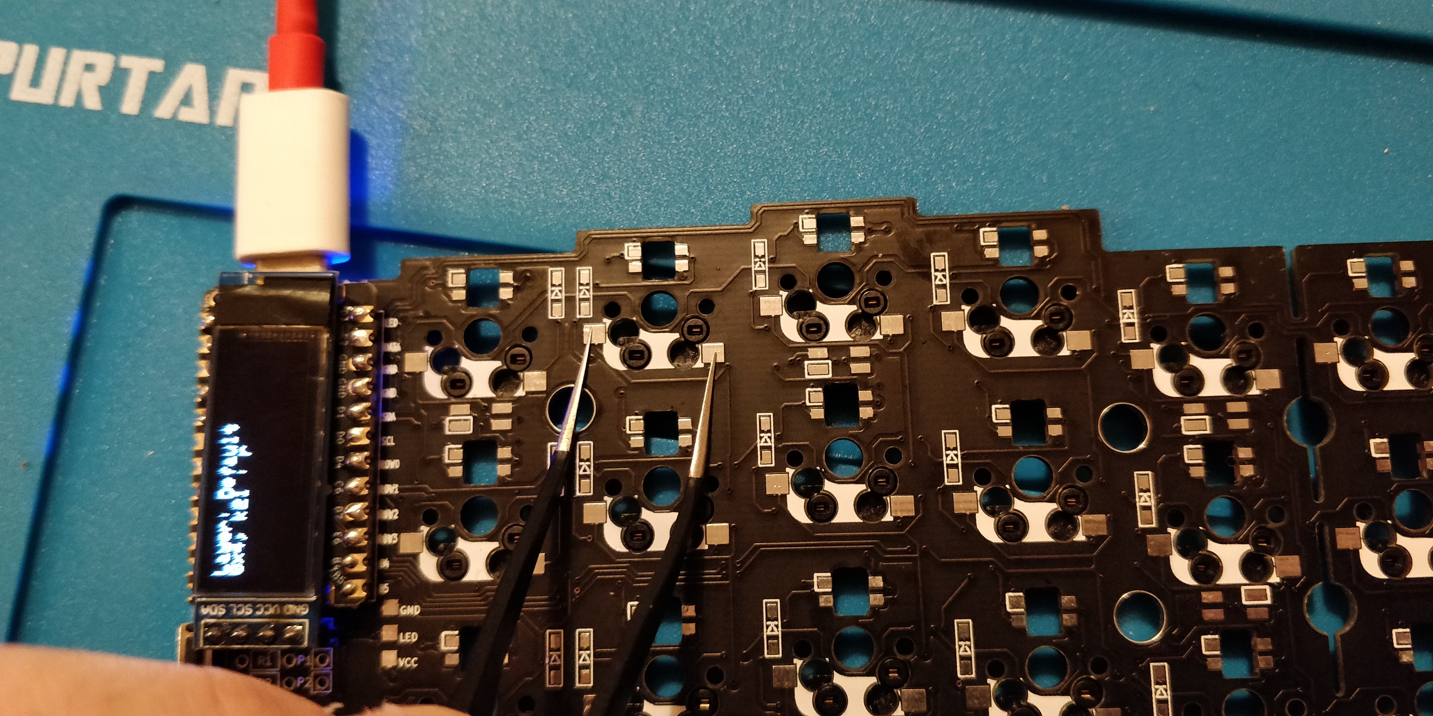
If all has gone well, the OLED screen should light up and you should see some debugging text on there relating to the 'Default' layer! Happy days. If not, make sure the OLED jumpers have been correctly shorted. You can now go through switch-by-switch and short the connection on the pads to simulate a keypress like in the image above.
I'm using the conductive ends of my tweezers to do this. If the diodes have been soldered correctly you should see the key information on the OLED display. If this doesn't happen for a particular key, check that the diode is the right way around and there are no cold solder joints. If you suspect it could be a soldering issue you can just reheat the solder with your iron to reflow the solder to fix a potentially cold joint.
Step 19. Tape down the TRRS jack for soldering
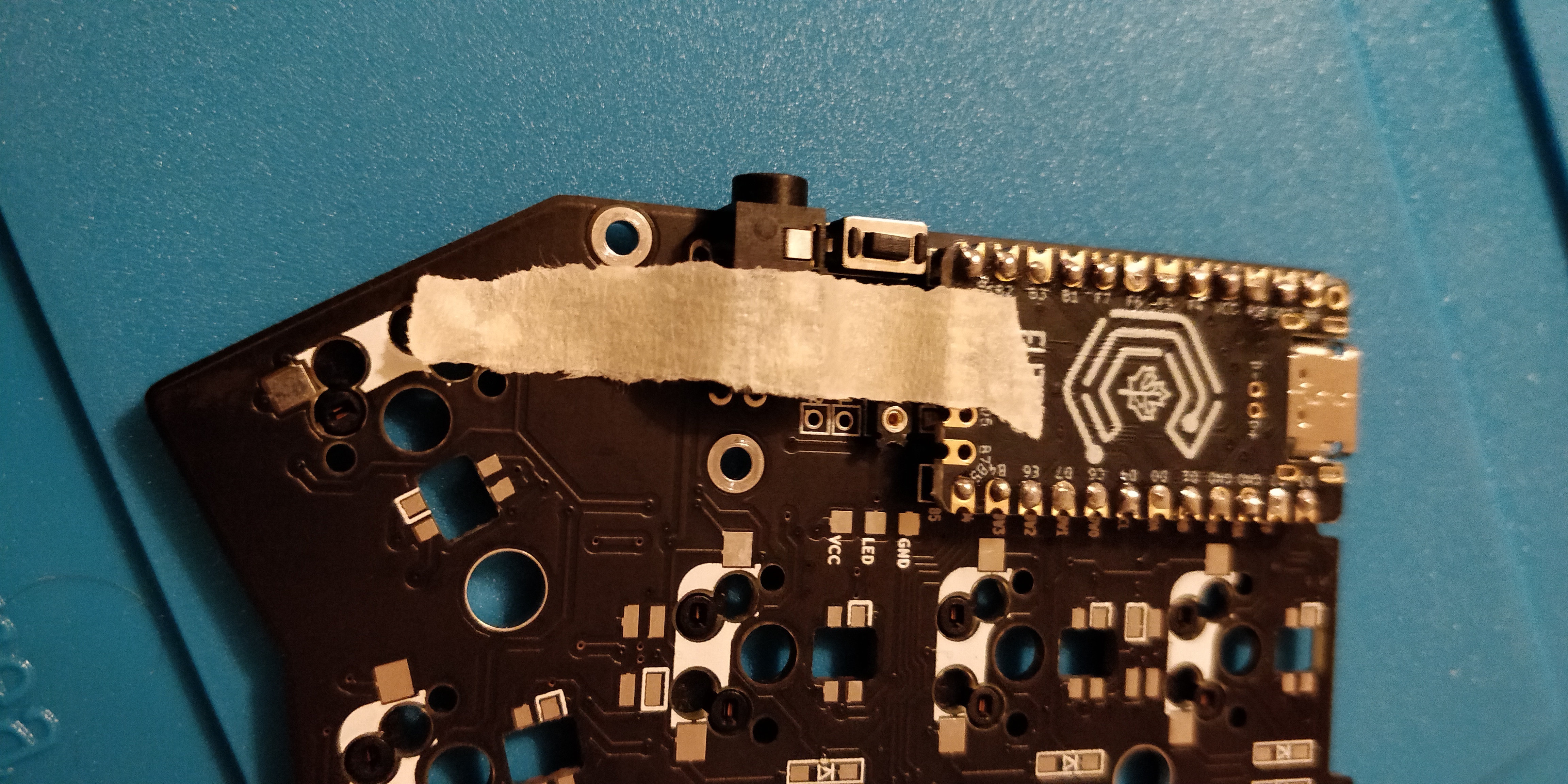
The TRRS jack is vital for the two halves of the keyboard to communicate with each other. Place the TRRS jack through the holes on the PCB, tape down to secure it in place and solder on the underside of the board.
If you have a reset button you can go ahead and solder this too. There should be space next to the TRRS jack for this marked out the PCB.
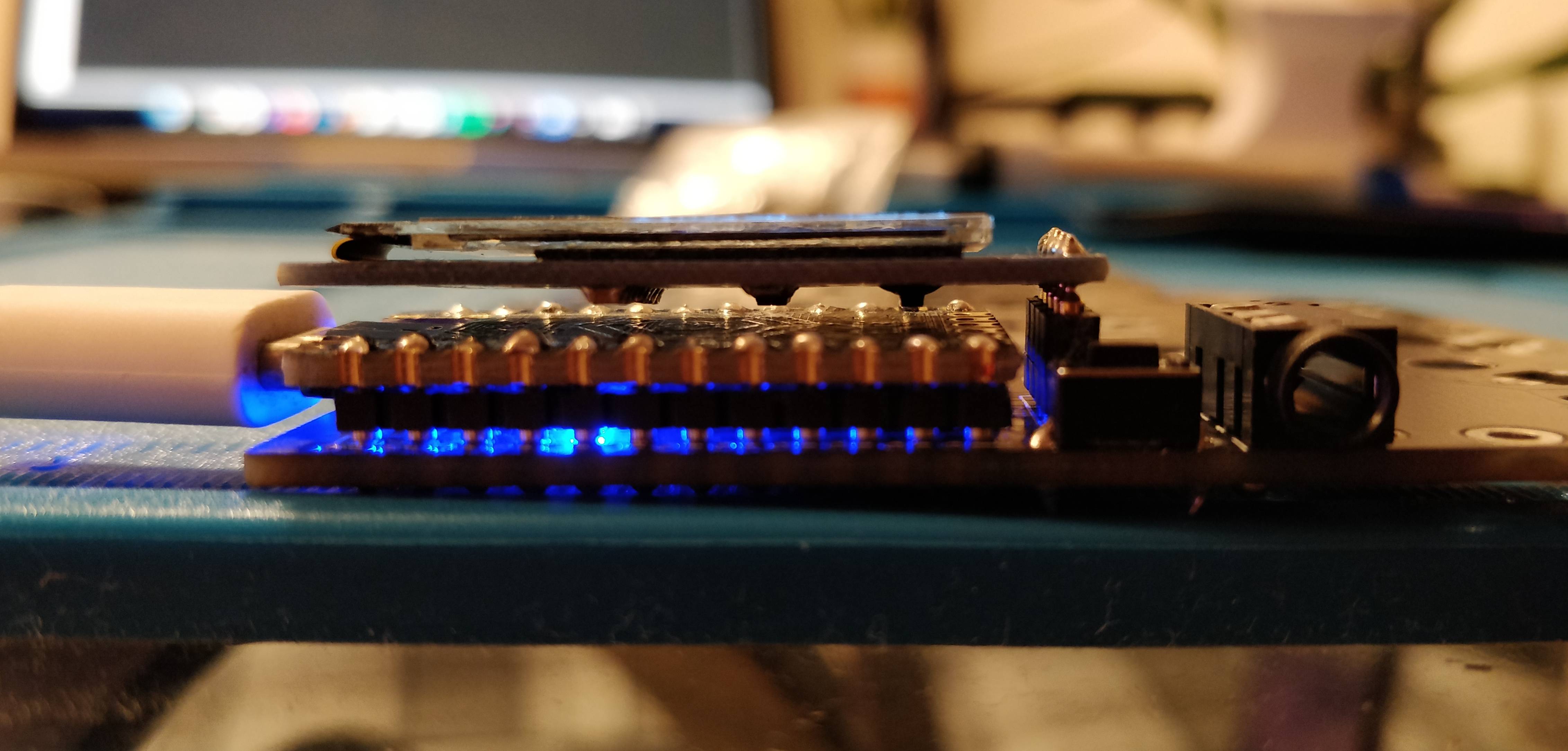
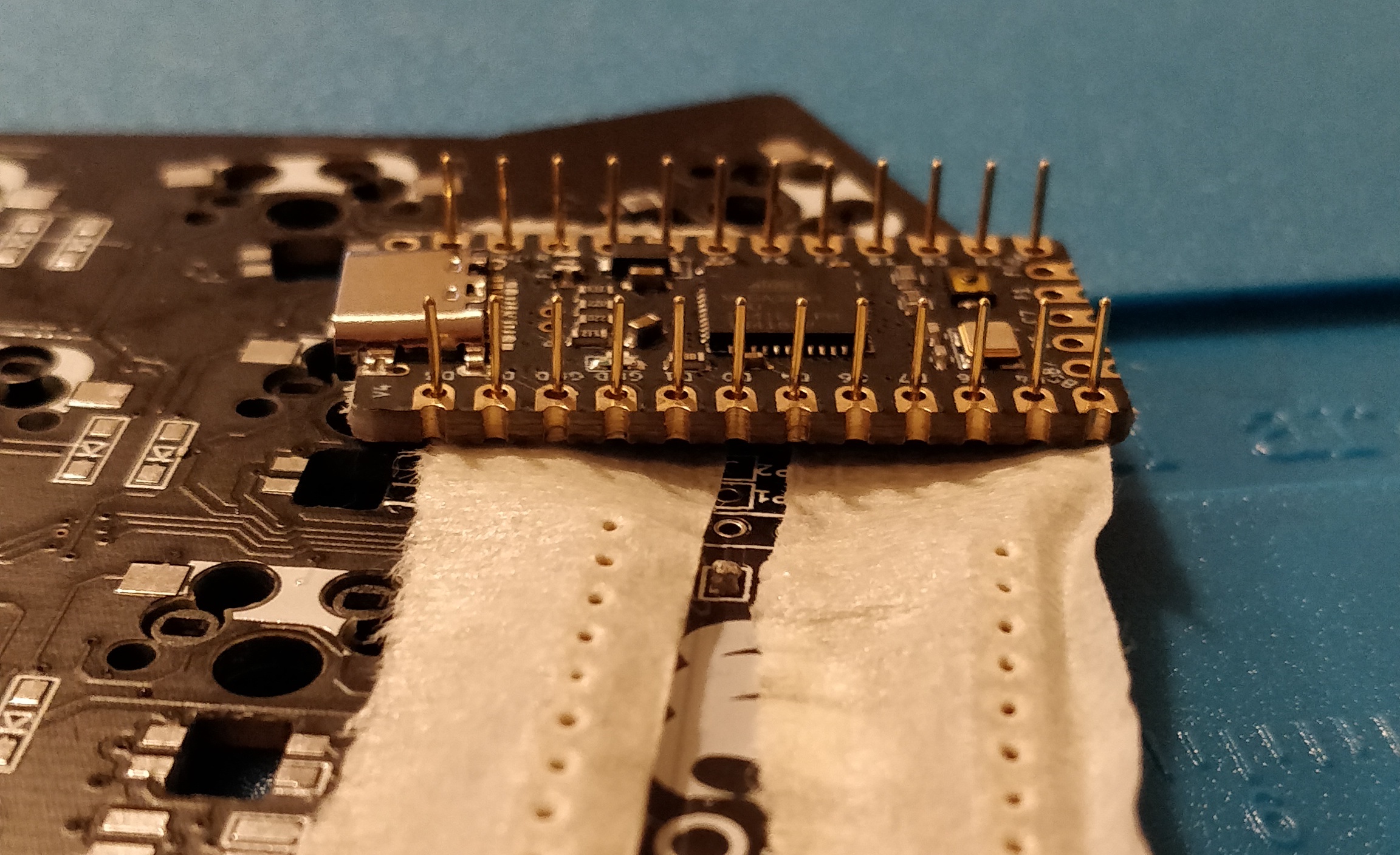
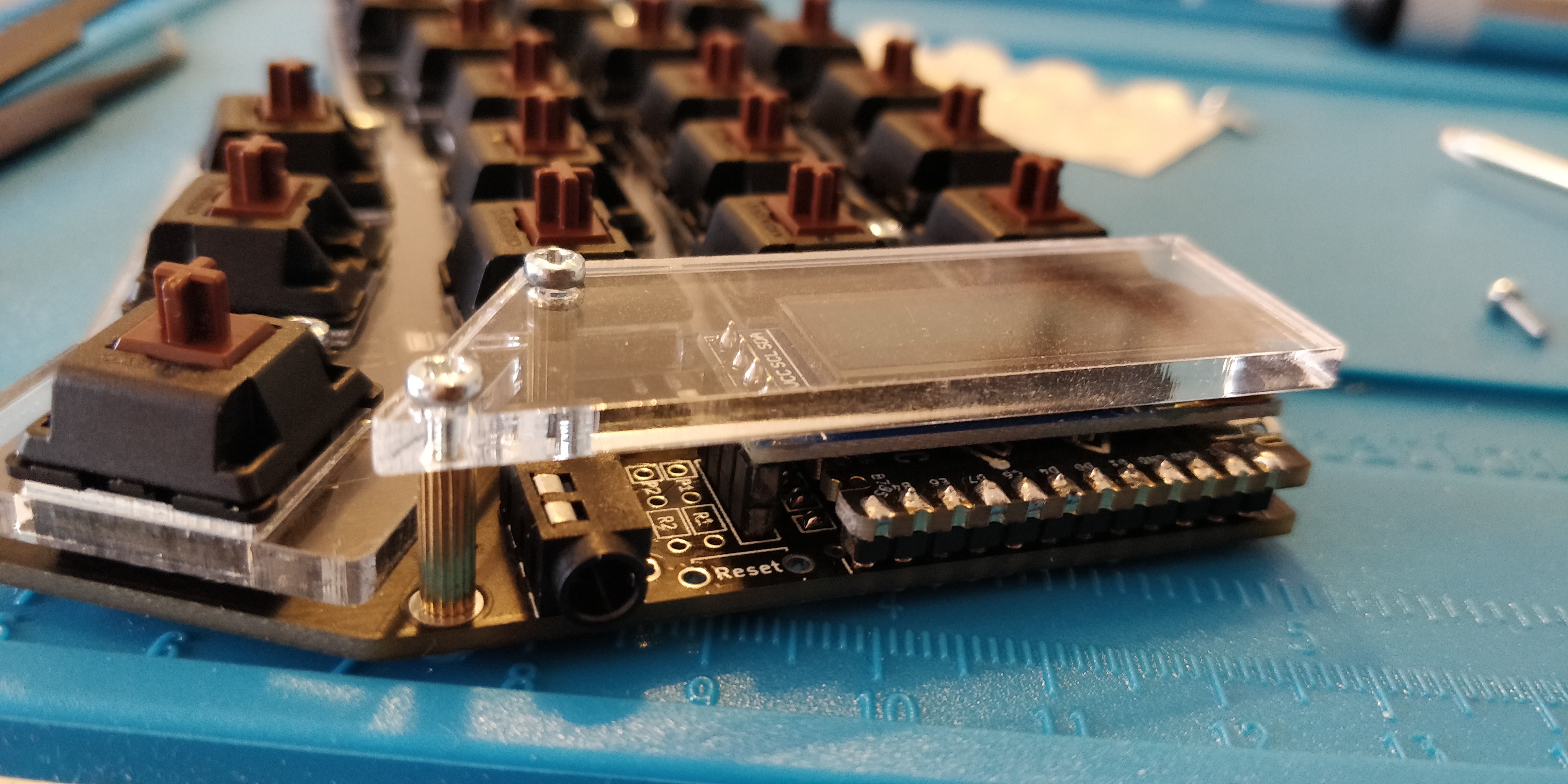
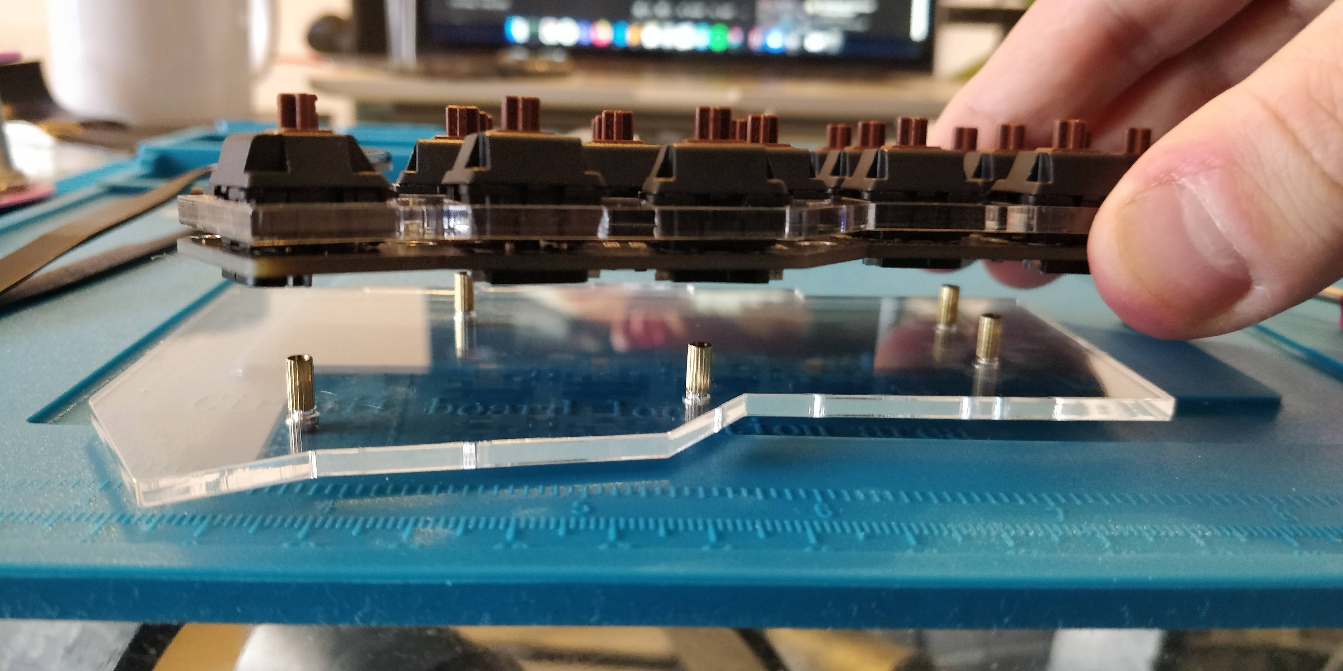
Congratulations! You have now completed one half of the keyboard. The side-view of the components should look like the one in the image above.
You now need to repeat the exact same steps for the other half of the keyboard making sure to create a mirror image.
Step 20. Connect both halves together via the TRRS
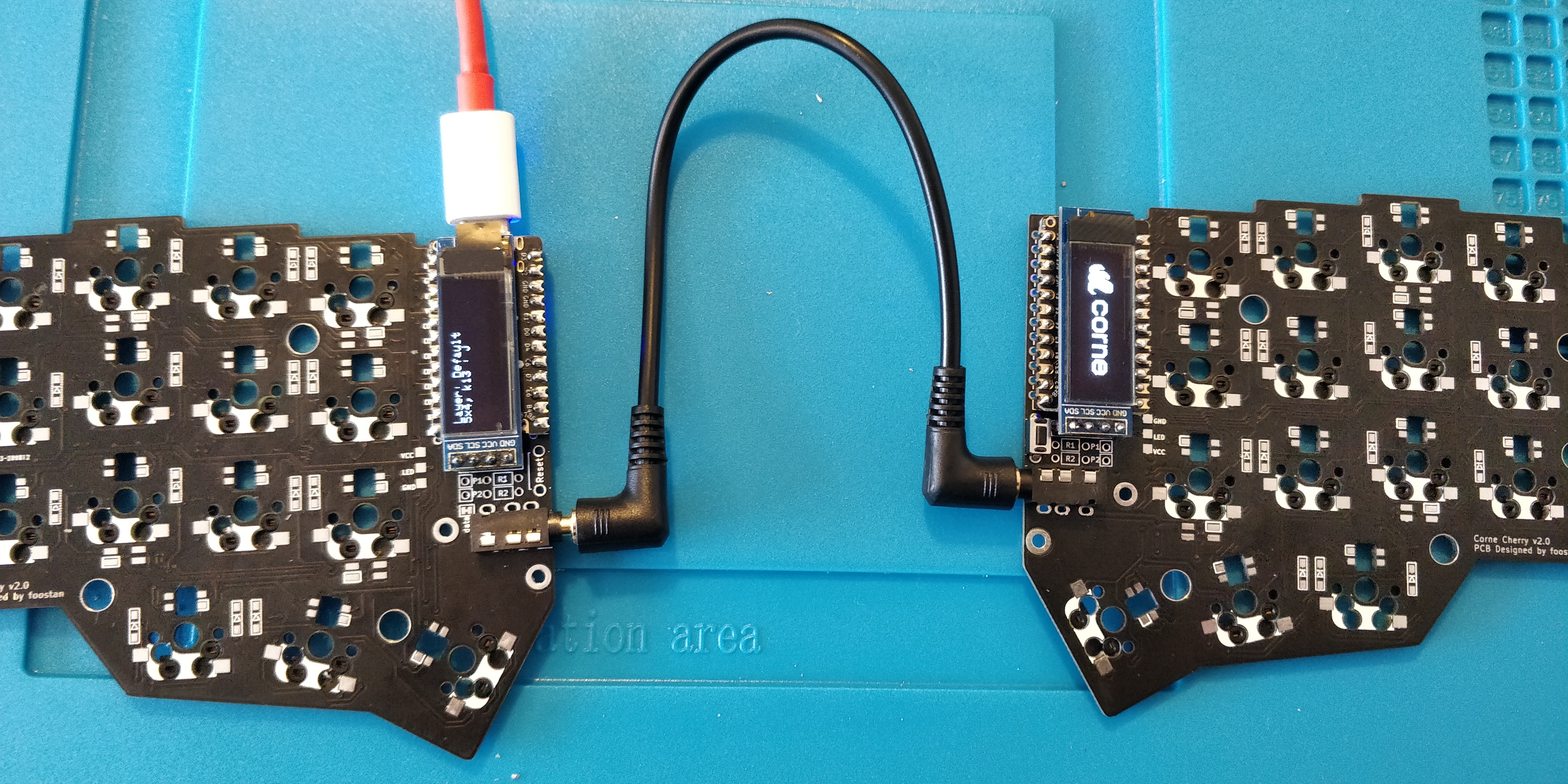
Once both halves of the keyboard have been soldered and verified to be working independently, we can now connect them together!
Take your TRRS cable and connect both halves through the TRRS jack and if both halves have been flashed with the firmware then you should see the correct keys shown on the OLED when shorted as I did on a previous step with metal tweezers.
Step 21. Push the switches through the acrylic plate
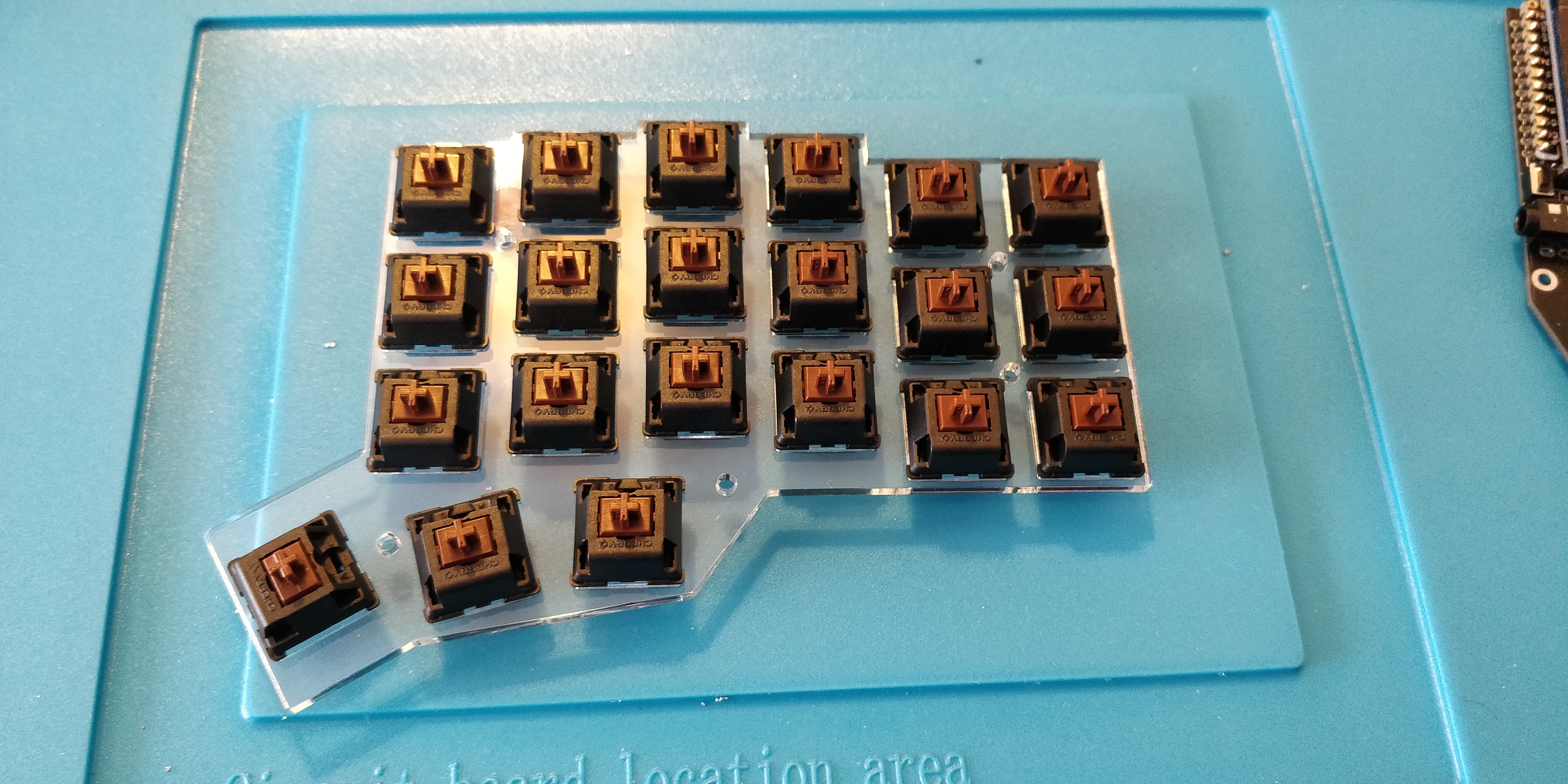
It's now time to build the case! Place your switches through each hole in the acrylic plate making sure that they're the right way around.
Step 22. Place the top plate over the PCB
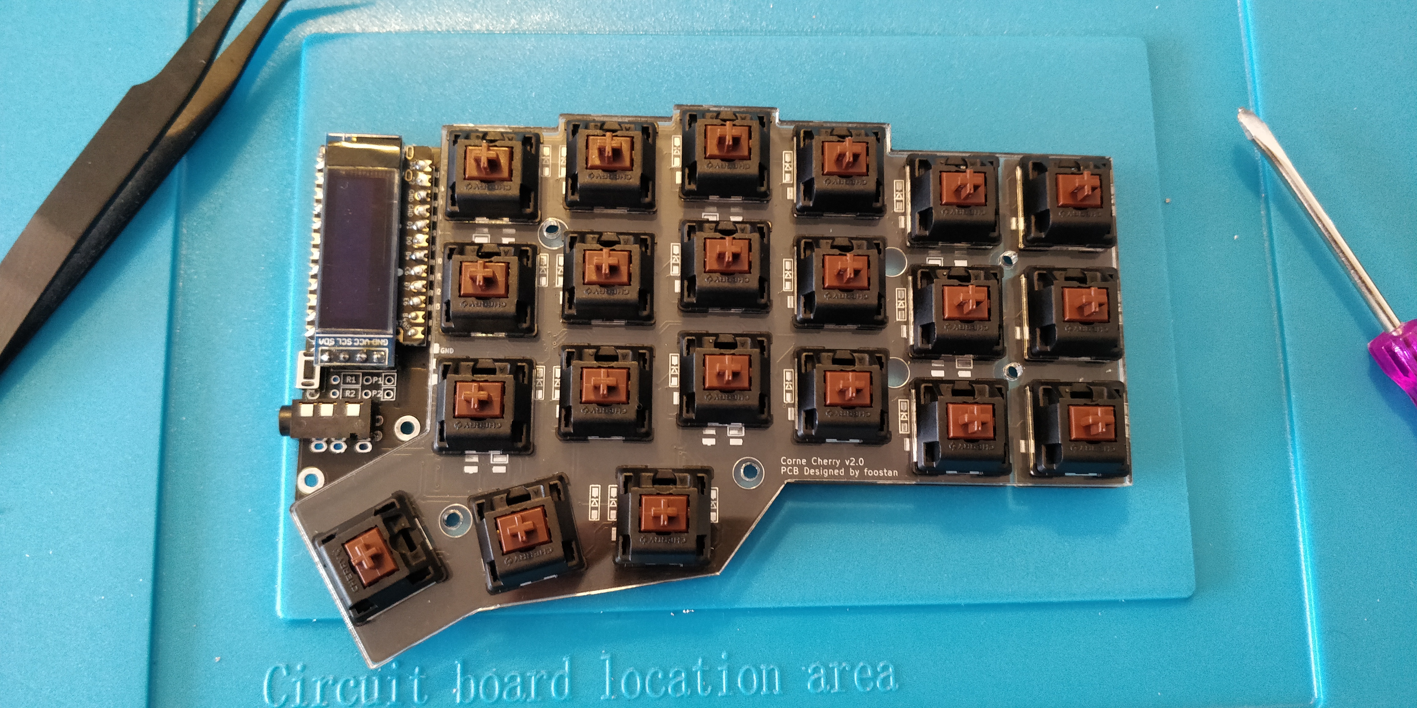
Place the top plate over the PCB and carefully push each switch into the hot-swap sockets that are exposed through the holes in the PCB. If the switches pop out don't worry, just insert them back in the plate and try again until they're all fully inserted.
Step 23. Screw the standoffs to the PCB and OLED cover
It's not absolutely necessary to screw in the OLED acrylic covers, but I want to protect this fragile part of the board for potential transportation.
I screwed the taller M2 standoffs to the PCB and the OLED cover.
Step 24. Screw the top and bottom plates together using the smaller M2 standoffs
The final part of the assembly requires you to use the smaller M2 standoffs to screw the top and bottom plates together through the wider holes on the PCB. These should all align for you!
Step 25. Add the flare 🕺
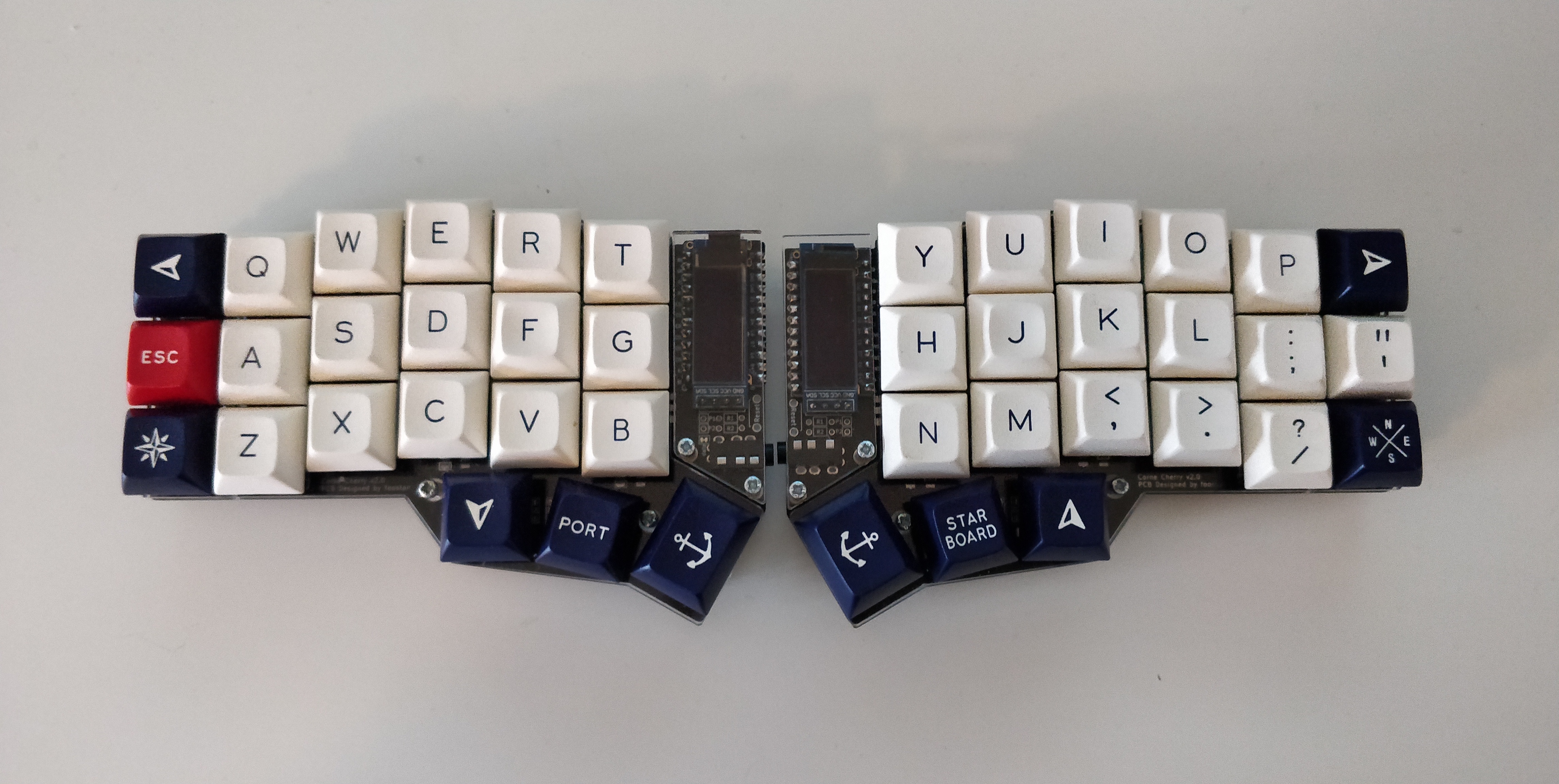
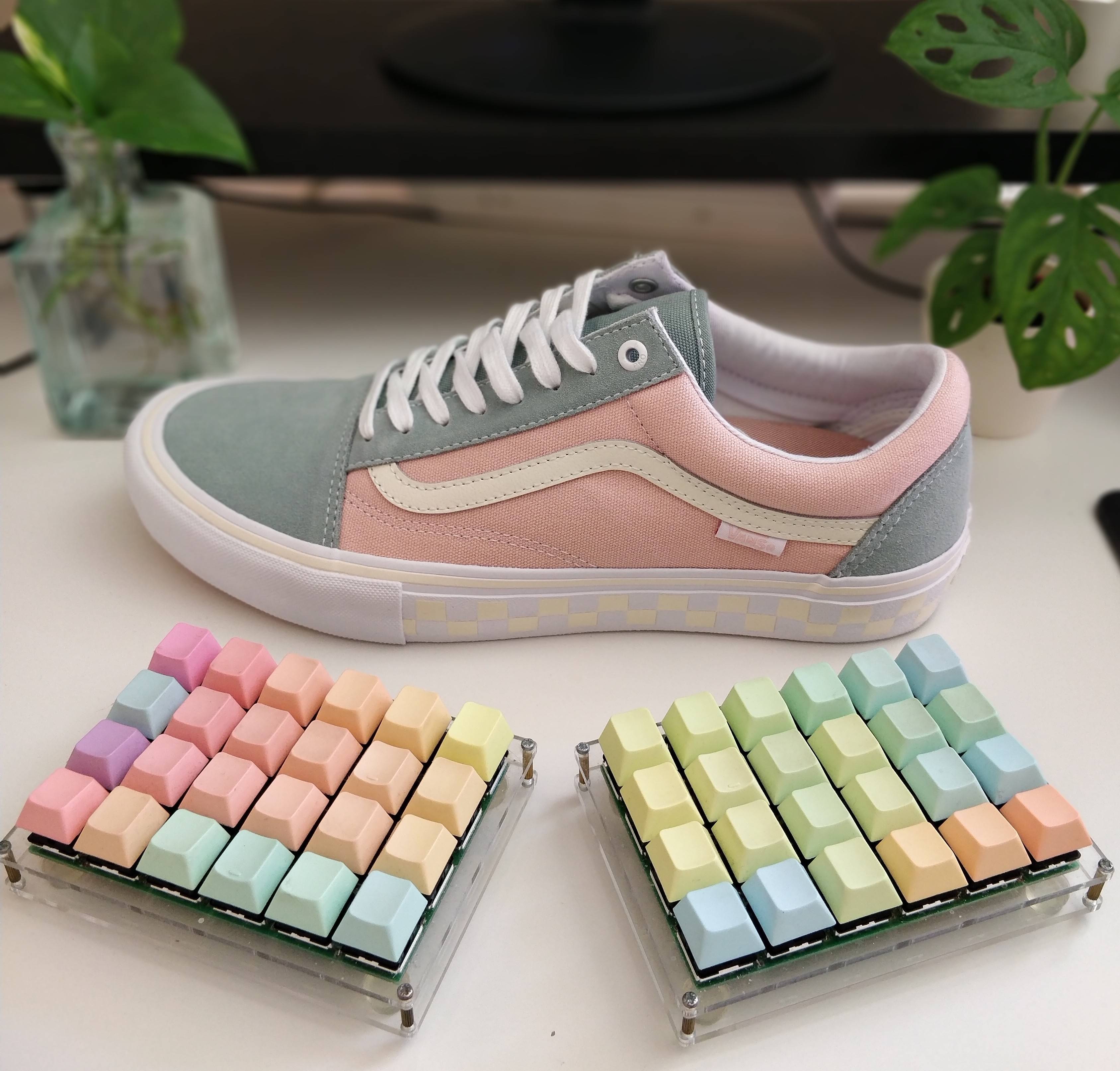
Dress it with your favourite keycaps and admire!
Mistakes that I made
Thanks for giving this section a read. I don't feel like too many people would be keen to showcase their mistakes but I hope the candidness of this is appreciated and you can learn from them.
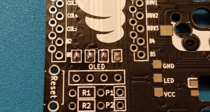
Mistake 1: Cold solder joints
Cold solder joints will give you frustration as you try to work out where they are. I mention it in the build guide above but it's really helpful to test this board as you go along to help zone in on mistakes early.
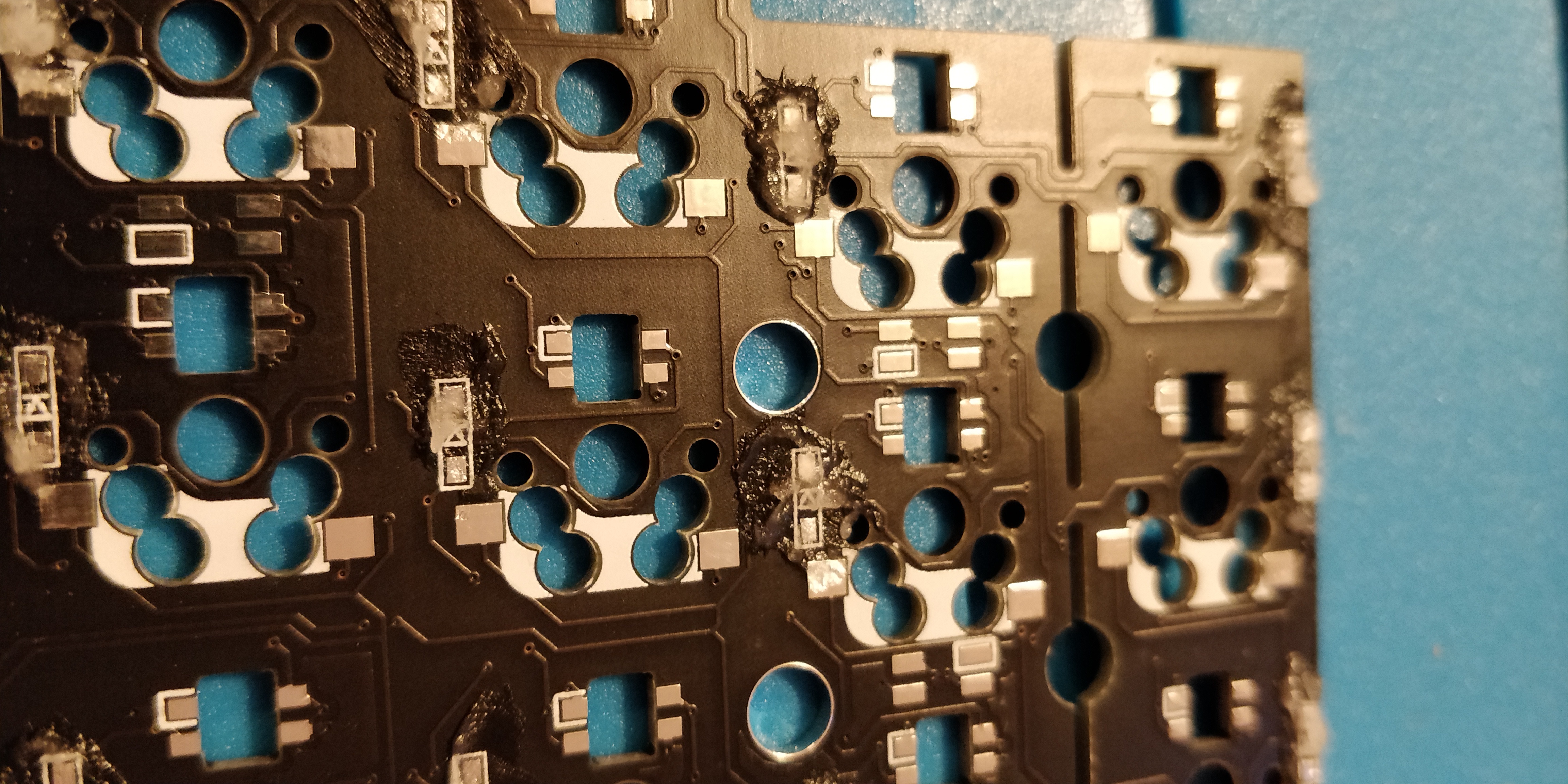
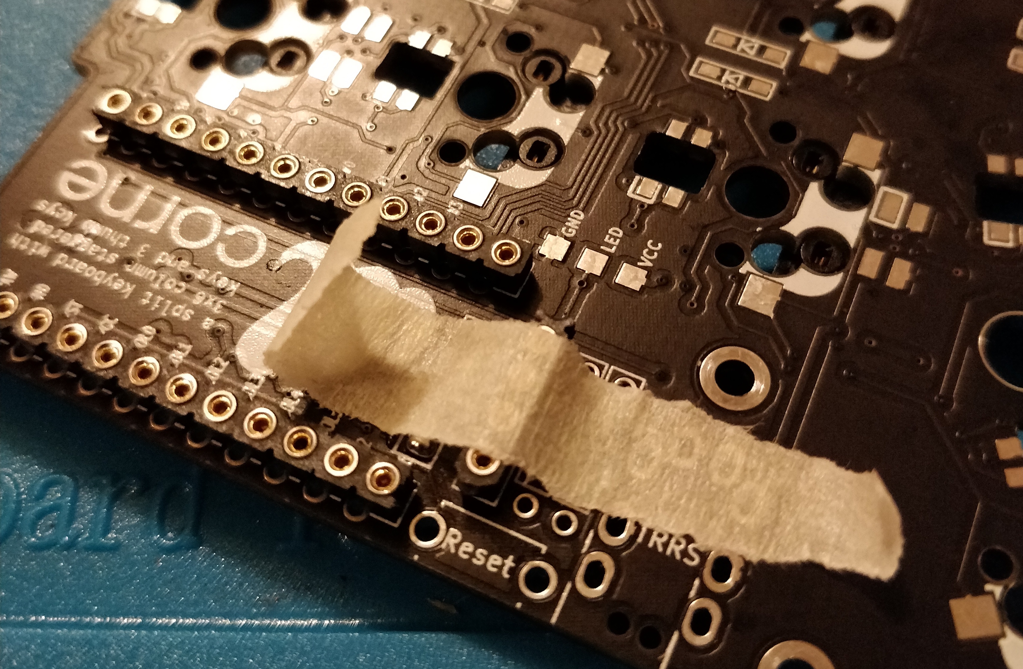
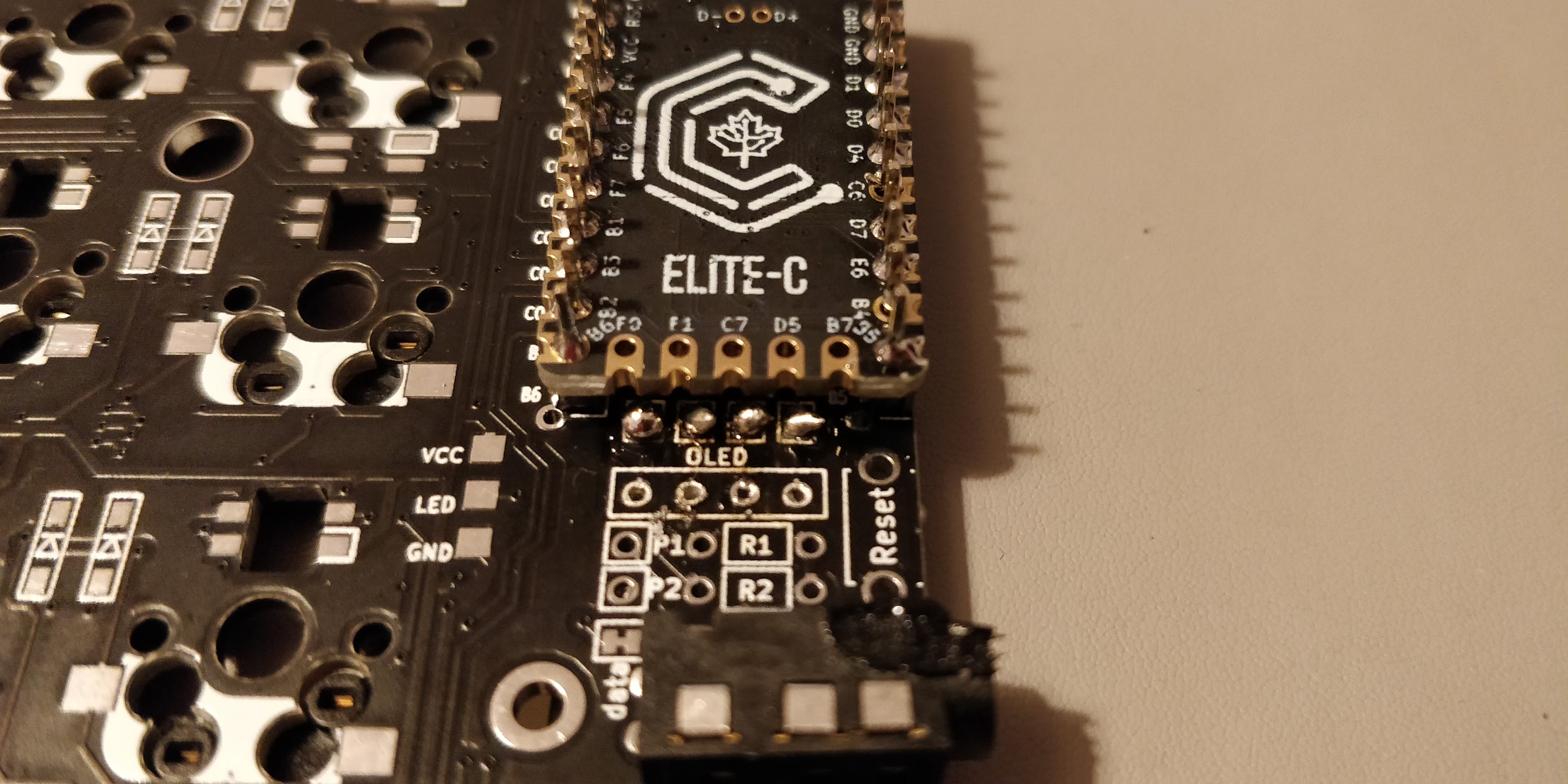
A cold joint is where the solder didn't quite melt properly which impacted the connection. In the image above you can see on certain pins like VCC1 and COL01 where the solder is sitting on the PCB loud and proud instead of flowing around the connection. I didn't notice this straight away and the impact was that both sides were only getting flashed with the left-hand side firmware.
Lesson: Practice soldering first and make sure that you can spot a bad joint! Here is a handy guide on what do to and what NOT to do.
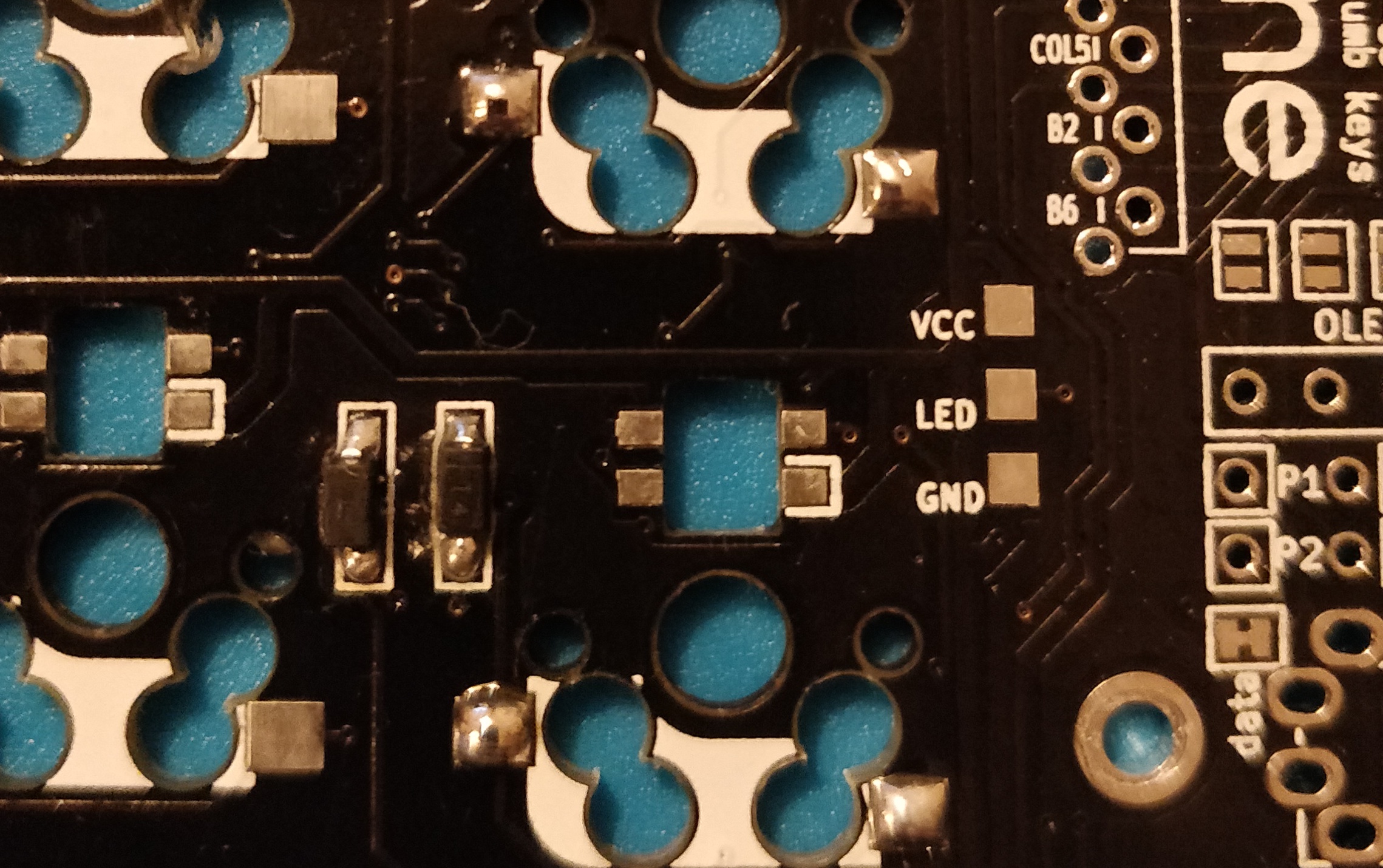
Mistake 2: Not soldering the OLED jumpers
So the OLED didn't work. After rereading the original build guide I discovered that I completely glossed over the part where I needed to solder and short circuit the jumpers. This was a problem as I had already soldered the OLED and the Elite-C in place without sockets and the jumpers were directly under the Elite-C. You can just about see them in the image above.
After managing to desolder the OLED header pins I had very limited access to the jumper pads, but thought that it may just be doable if I carefully solder with a fine solder nib. It looks like it probably would have worked now, right? Almost definitely.

That is of course until I tried to improve that probability. I ended up making a dog's dinner out of it by fusing solder balls and what looks like burning the jumper pad off the board completely no doubt due to my numerous attempts to salvage it. I cut my losses and ordered new parts to start again.
Lesson: Read the manual! Also, it's a good idea to socket the microcontroller for easy removal. If I did this then there would have been no issue. I cover this in Mistake 3.
Mistake 3: Not socketing the microcontroller and OLED
In the Mistake 2 section above I had to desolder the OLED headers and would have benefitted by being able to easily remove the microcontroller. The build guide shows the steps to socket the microcontroller meaning it can be easily removed but it was a big mistake to use the default header pins on my first attempt.
Lesson: If you can socket a component especially if it's complicated with many pins, socket it. If it's a component that can break and might need replacing, again, socket it.
Mistake 4: Soldering without flux
Flux helps to promote the flow of solder and helps it 'stick' to pads and connections. I didn't use any additional flux aside from the flux contained within the solder itself. On my first attempt the result was more blob-like soldering with some instances of burnt pads where the solder didn't initially stick to it. This is in part due to a bad soldering technique but using flux helped massively and created neater joints.
Lesson: Flux makes everything easier. Use where possible especially on surface-mounted components.
Final thoughts and learnings
This keyboard was both enjoyable and challenging to build. It required a lot more thought and care with regards to soldering, handling of components and the importance of socketing the microcontroller was regrettably highlighted to me after my first attempt. My top learnings were:
- Flux is incredibly useful for precise soldering
- Socketing a microcontroller can save lots of pain desoldering in the event of mistakes
- Correct soldering technique prevents cold joints. Finding the cold joints was difficult and testing little and often helps isolate issues
- Read build guides carefully! Most of my original mistakes were preventable by simply paying attention
- Sometimes you have to admit defeat. My first attempt included LEDs that require another level of skill to solder due to their temperature sensitivity. However, after all but one spontaneously stopped working overnight I decided that they weren't worth it for me. I might add them at some stage and update this build log
Thank you for reading and I hope you found this useful. Please feel free to ask any questions in the comments below and I'll try to help as much as possible.


